1-14 (No.MB616<Rev.002>)
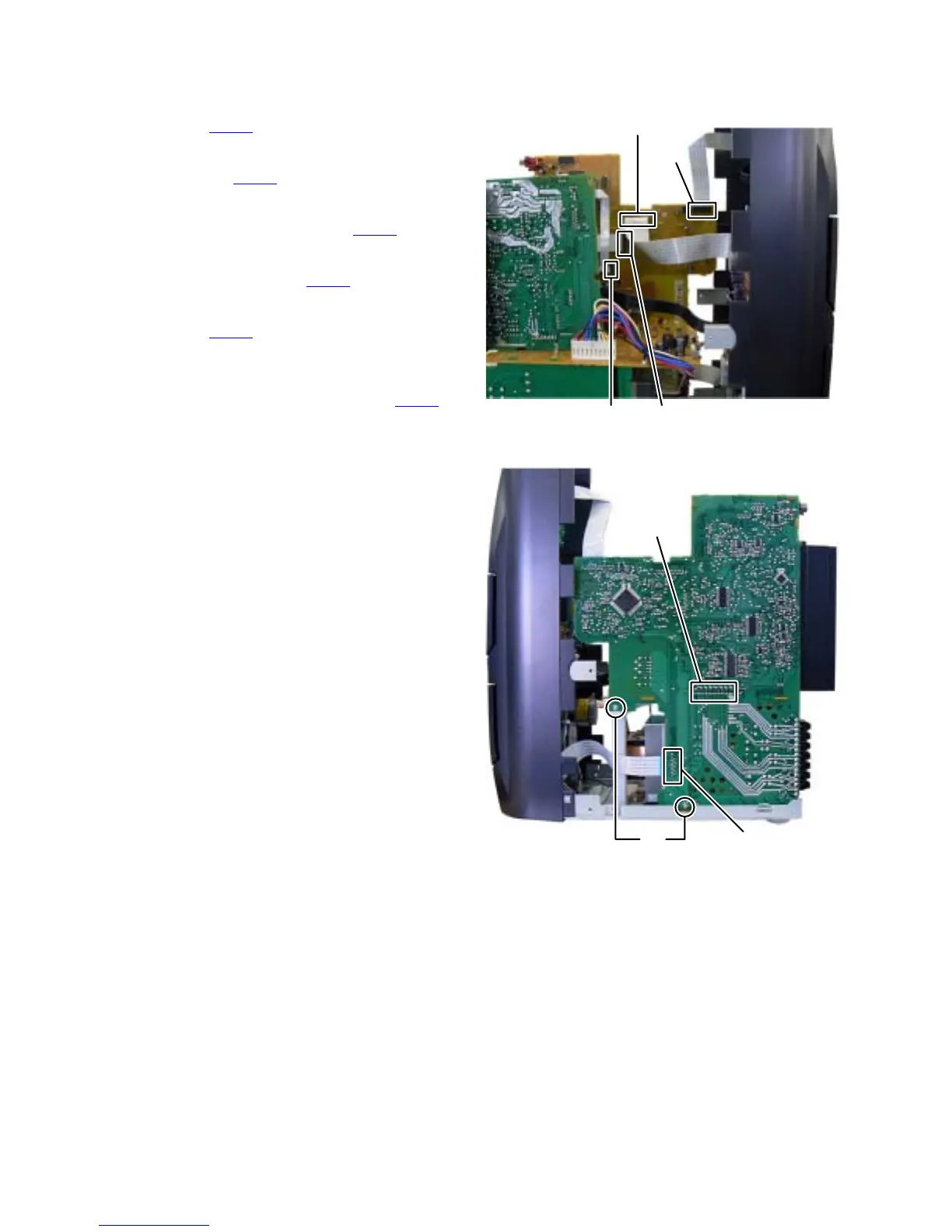
3.1.8 Removing the MAIN BOARD assembly
(See Fig.17, 18)
(1) Disconnect the card wire from FL BOARD assembly con-
nected to connector CN720 of the MAIN BOARD assem-
bly. (See Fig.17)
(2) Disconnect the card wire from CASSETTE MECHANISM A
connected to connector CN730
of the MAIN BOARD as-
sembly. (See Fig.17)
(3) Disconnect the card wire from SUBWOOFER AMP
BOARD assembly connected to connector CN820
of the
MAIN BOARD assembly. (See Fig.17)
(4) Disconnect the card wire from SURROUND AMP BOARD
assembly connected to connector CN830
of the MAIN
BOARD assembly. (See Fig.17)
(5) Disconnect the card wire from MIC BOARD assembly con-
nected to connector CN740
of the MAIN BOARD assem-
bly. (See Fig.18)
(6) Remove the two screws L attaching the MAIN BOARD as-
sembly. (See Fig.18)
(7) Disconnect the BOARD TO BOARD connector CN850
connected the MAIN BOARD assembly and REGULATOR
BOARD assembly. (See Fig.18)
Fig.17
Fig.18
CN730
CN720
CN820 CN830
CN740
CN850
L
 Loading...