1-26 (No.MB616<Rev.002>)
3.2.9 Removing the spindle motor board
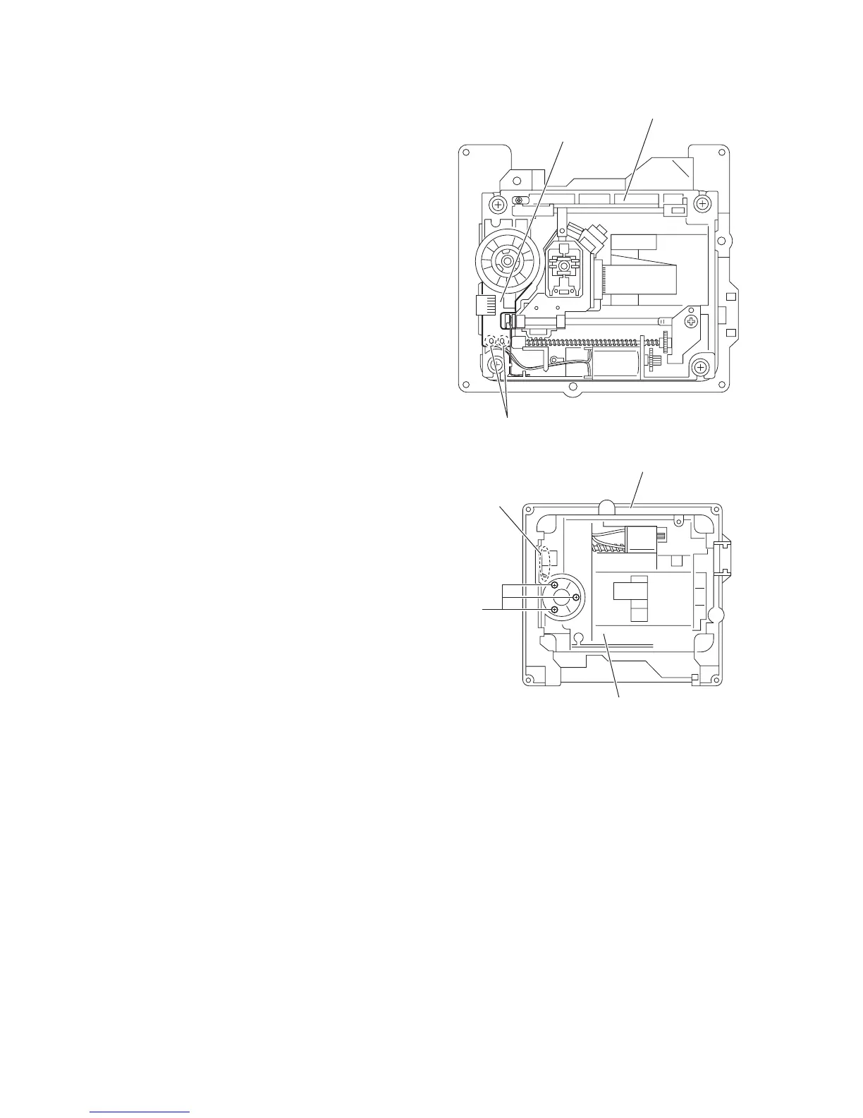
(See Figs.16 and 17)
• Remove the tray assemblies, DVD servo board and DVD
traverse mechanism assembly.
(1) From the top side of the DVD traverse mechanism assem-
bly, remove the wires from the soldered sections r on the
spindle motor board. (See Fig.16.)
(2) From the bottom side of the DVD traverse mechanism as-
sembly, remove the three screws J attaching the spindle
motor board. (See Fig.17.)
Reference:
When attaching the spindle motor board, let the card wire
through the hole s on the C.TM chassis. (See Fig.17.)
Fig.16
Fig.17
r
Spindle motor board
DVD traverse mechanism assembly
J
C.TM chassis
DVD traverse mechanism assembly
s
 Loading...