1-8
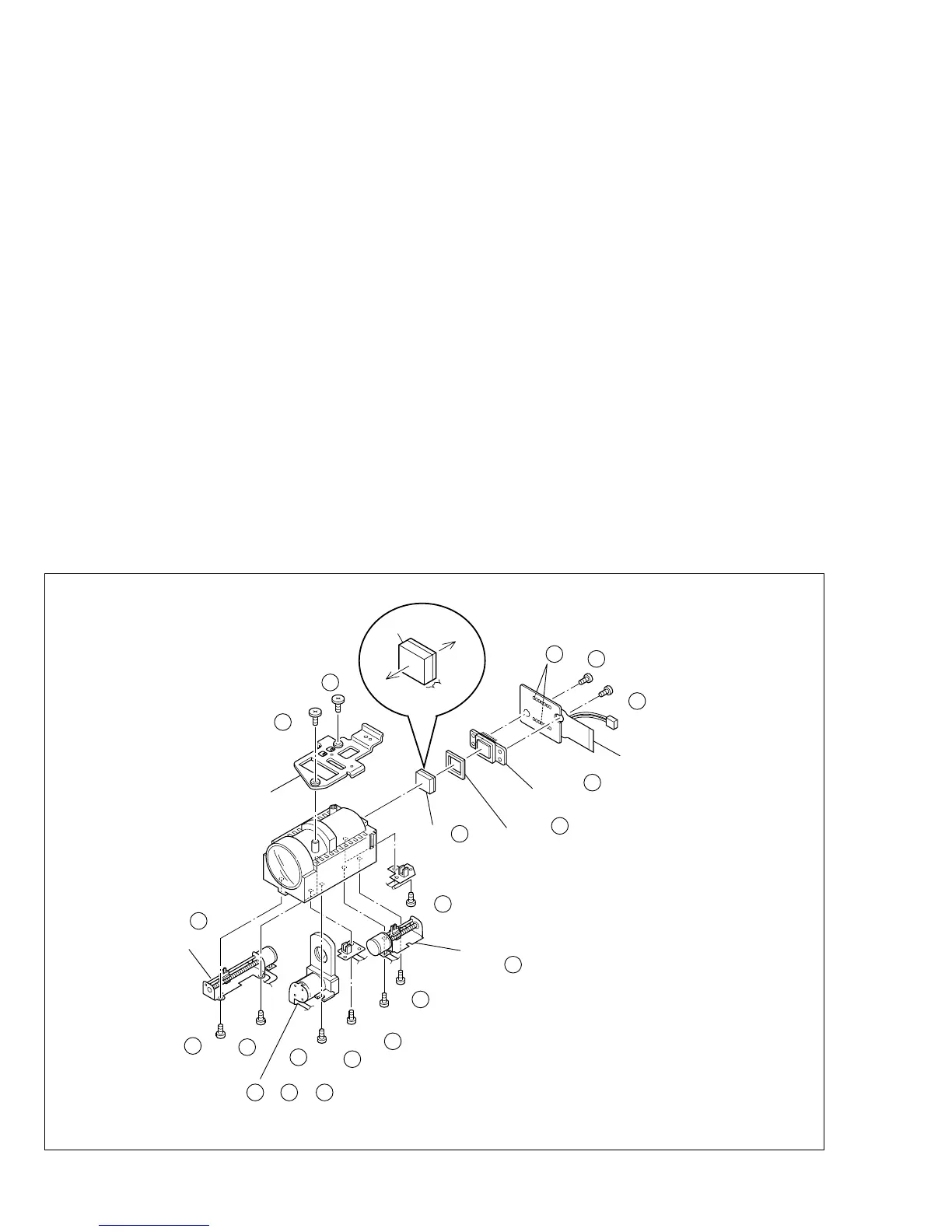
Fig. 1-4-1
1.4 DISASSEMBLY OF THE
4
OP BLOCK AND CCD
BOARD ASSEMBLIES
1.4.1 Precautions
1. Take care in handling the CCD image sensor, optical LPF
and lens components2when performing maintenance
etc., especially with regard to surface contamination, at-
tached dust or scratching. If fingerprints are present on
the surface they should be wiped away using either a
silicon paper, clean chamois or the cleaning cloth rec-
ommended by the Video Product Division.
2. The CCD image sensor may have been shipped with a
protective sheet attached to the transmitting glass. When
replacing the CCD image sensor, do not peel off this
sheet from the new part until immediately before it is
mounted in the OP Block Assembly.
1.4.2 How to remove
1. Remove the solder (SD1) from the 16 soldered points
on the CCD Board Assembly and take the assembly out.
2. Remove the two screws (1, 2) and take out the CCD Base
Assembly.
Note
4
a:
When removing the CCD Base Assembly, be
careful not to take out the CCD image sensor to-
gether with the spacer rubbers attached to it.
Note
4
b:
The CCD image sensor should not be replaced
as a single part but should be replaced together
with the entire CCD Base Assembly.
1.4.3 How to install
1. With the spacer rubbers attached to the CCD base,
mount the CCD base in the OP Block Assembly and
tighten them together using the two screws (1, 2).
2. Mount the CCD Board Assembly and attach solder to
the 16 points (SD1).
1.4.4 Replacement of Service Repair Parts
The service repair parts for the OP Block Assembly are as
listed below.
Before replacement of these parts, remove the bracket (OP
assyembly) as required.
Take special care not to disconnect any of the FPC wires
or cause any damage due to soldering (excessive heat-
ing).
1. Focusing motor
2. Zoom motor
3. Iris motor unit
Note
4
c:
When replacing the focusing motor or the zoom
motor, solder the FPC at a space of about 1 mm
above the terminal pin.
When assembling, make sure that the slide sec-
tion is positioned correctly.
Note
4
d:
The iris motor unit includes the FPC Assembly,
switch and two sensors.
Note
4
e:
Be careful not to damage the switch.
3
(S c)
4
4
(S c)
4
2
(S a)
4
1
(S a)
4
(SD 1 )
NOTE 4 b
OP
side
BRAKET (OP) ASSY
ZOOM MOTOR
IRIS MOTOR UNIT
FOCUS MOTOR
SPACER RUBBER
OPTICAL LPF
BASE ASSY
CCD BORD ASSY
BLUE
THIN
THICK
CCD
side
NOTE 4 a
NOTE 4 a
9
(S c)
4
NOTE 4 c
∗ : 0.118 N
•
m (1.2kgf
•
cm)
∗∗ : 0.147 N
•
m (1.5kgf
•
cm)
NOTE 4 c/ 4 d/ 4 e
10
(S b)
4
8
(S d)
4
5
(S c)
4
6
(S c)
4
11
(S b)
4
7
(S d)
4
NOTE 4 c
∗
∗
∗
∗
∗
∗
∗
∗∗
∗∗
∗
∗
 Loading...