1-9
FPC ASSY
7
(S d)
7
6
(S c)
7
5
(S c)
7
3
(S b)
7
4
(S b)
7
1
(S a)
7
10
(S e)
7
8
(S e)
7
9
(S e)
7
11
(S e)
7
2
(S a)
7
NOTE a
7
NOTE b
7
∗
: 0.059 N
•
m (0.6kgf
•
cm)
12
(S e)
7
∗
∗
∗
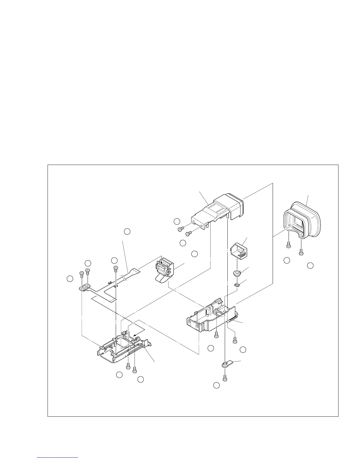
EYE CUP
UPPER CASE ASSY
LCD UNIT
HOLD ASSY
(for lens)
LINK
(for lens)
Wave
washer
BOTTOM CASE ASSY
BRACKET (VF) ASSY
LEVER (for lens)
Fig. 1-5-1
1.5
7
E.VF(COLOR)
1.5.1. Disassembly/Assembly of the
7
E.VF(COLOR)
1. Remove the two screws (1 and 2) and then remove the
EYE CUP.
2. Remove the two screws (3 and 4).
3. Pull out the VF assembly and then remove the three
screws (5 to 7) to release the FPC ASSY.
4. Remove the two screws (8 and 9) then lift the E.VF from
the BRACKET (VF) ASSY and take out the FPC ASSY.
Note
7
a :
Be careful not to disconnect or break the FPC
ASSY wire.
5. Remove the two screws (10 and 11) to remove the UP-
PER CASE ASSY.
6. Remove the LCD UNIT from the BOTTOM CASE ASSY.
Note
7
b :
Refer to the parts list for detail of the parts.
7. Remove the screw (12) and then remove the HOLD ASSY
(for lens), LINK (for lens), wave washer, LEVER (for lens).
 Loading...