2-20
2.8.1 Tape pattern check
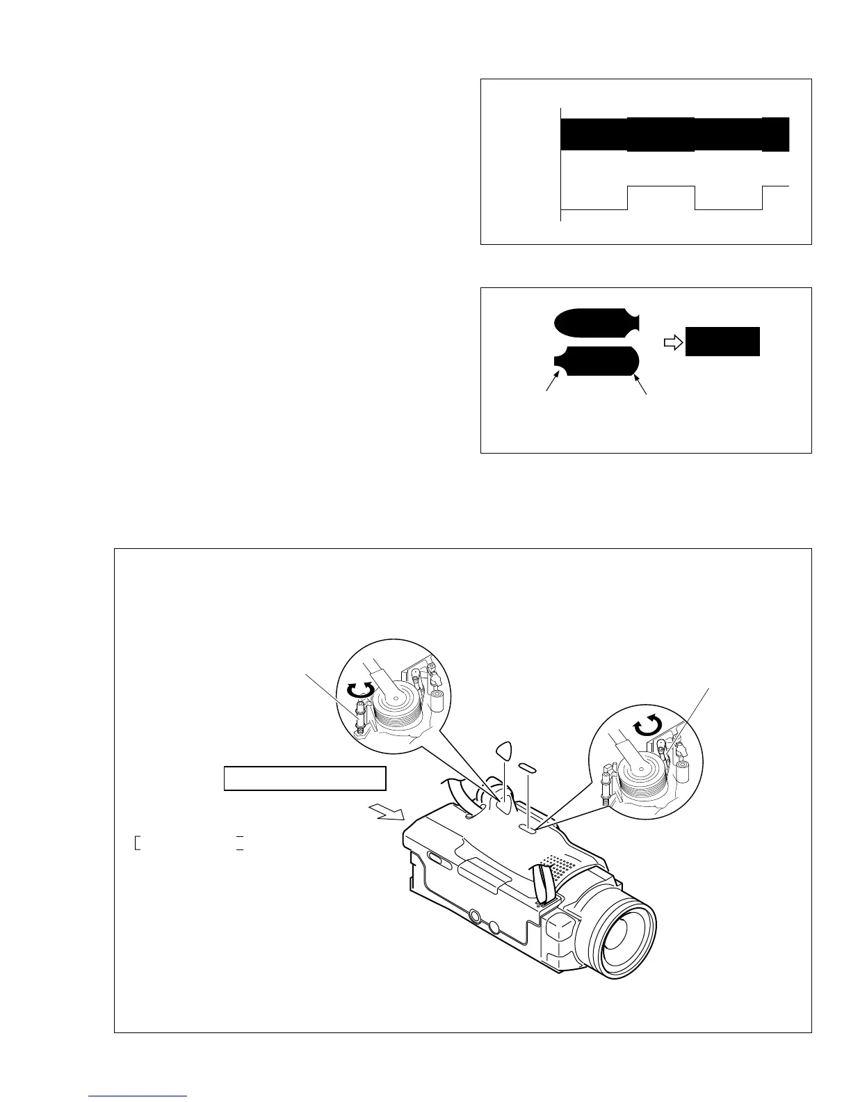
(1) Play back the compatibility adjustment tape.
(2) While triggering the MAIN CN107-10PIN (HID1), ob-
serve the waveform of CN107-26PIN (ENV_OUT).
(3) Confirm that the waveform is free from remarkable
level-down, and entirely parallel and straight.
Moreover, perform the following adjustment as re-
quired.
(4) In case any level-down is observed on the left hand
side, straighten the level by turning the guide roller of
the pole base assembly (supply).
In case any level-down is observed on the right hand
side, however, straighten the level by turning the guide
roller of the pole base assembly (Take-up).
(5) After adjustment, try the unloading motion once, and
confirm that the waveform is flat (straight) when the
tape has been played back again.
Moreover, perform readjustment as required.
(6) When the recording has been played back again, play
back the self-recording to confirm that the waveform
is flat.
Fig. 2-8-3
Fig. 2-8-4
Fig. 2-8-5
CN107
(ENV_OUT)
CN107
(HID1)
Flatten the waveform.
Misalignment of guide roller
height on the take-up side
Misalignment of guide
roller height on the
supply side
COVER
(Cassette)
COVER
(Cassette
rear)
Refer to page 2-19.
MAIN CN107
26PIN (ENV_OUT)
10PIN (HID1)
JIG CONNECTOR CABLE
JIG CONN. BOARD
JIG CONN-26PIN (ENV_OUT)
JIG CONN-10PIN (HID1)
GUIDE ROLLER
(SUP) ASSY
NOTE:
The two covers serve as the covers for the
service adjustment access holes.
GUIDE ROLLER (TU) ASSY
Note:
When an adjustment is performed with the lower case cover
attached, first slide the two covers (cassette and cassette
rear) open and then perform the compatibility adjustment.
Be sure not to damage the covers when sliding them open
to make an adjustment because they must be re-positioned
after completing the adjustment.
 Loading...