(No.HC047<Rev.001>)1-5
SECTION 2
SPECIFIC SERVICE INSTRUCTIONS
This service manual does not describe SPECIFIC SERVICE INSTRUCTIONS.
SECTION 3
DISASSEMBLY
3.1 Center frame section
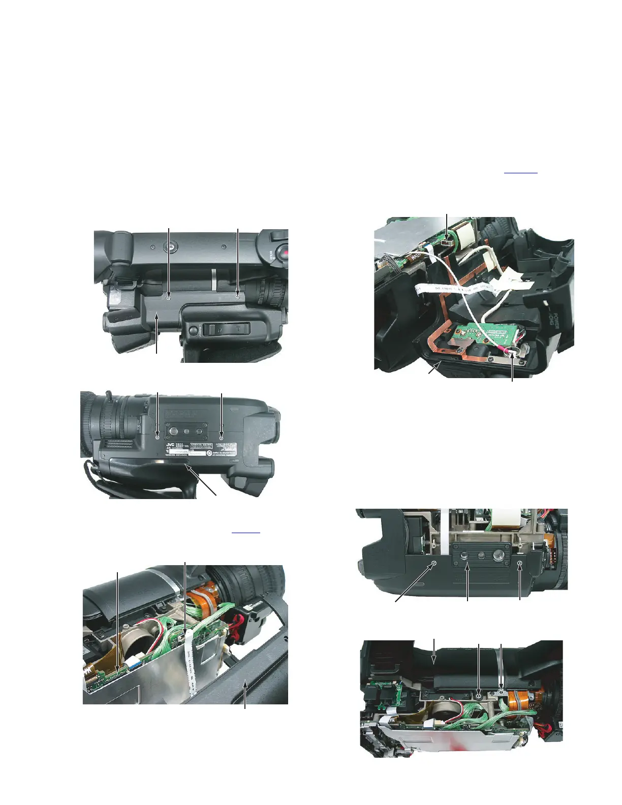
3.1.1 Removing the L side cover assembly (See Figure 1, 2,
3 and 4)
(1) Remove the four screws A attaching the L side cover as-
sembly, and then open the L side cover assembly.
Fig.1
Fig.2
(2) Pull out the wire from the connector CN210
on the MAIN
board.
Fig.3
(3) Pull out the wire from the SDI terminal.
(4) Pull out the wire from the connector CN3112
on the NET-
WORK board, and then remove the L side cover assembly
(only GY-HM650).
Fig.4
3.1.2 Removing the R side cover assembly (See Figure 5, 6,
7 and 8)
• Remove the L side cover assembly.
(1) Remove the four screws B and the one screw C attaching
the R side cover assembly.
Screw B: Short Screw C: Long
(2) Remove the two screws D attaching the handle cover (R)
and then remove the handle cover (R).
Fig.5
Fig.6
A
L Side cover assembly
A
AA
L Side cover assembly
CN210
MAIN Board
L Side cover assembly
CN3112
SDI Terminal
L Side cover assembly
BBR Side cover assembly
R Side cover assembly
BB
 Loading...