(No.MA140)1-17
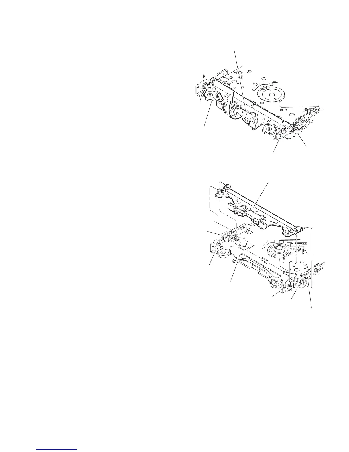
3.2.7 Removing the loading arm assembly
(See Figs.13 and 14)
• Remove the mechanism control board, top cover, mechanism
section and front unit 2.
(1) From top side of the mechanism section, move the loading
arm assembly in the direction of the arrow. (See Fig.13.)
(2) Release the projections from the right and left joints (m, n)
of the CD chassis assembly. (See Figs.13 and 14.)
(3) Release the projection from notch p of the connect arm on
the right side of the mechanism section and release the
projection from notch q of the slide cam assembly on the
left side. (See Figs.13 and 14.)
Fig.13
Fig.14
m
p
n
Loading arm assembly
CD chassis assembly
m
p
n
Loading arm assembly
q
Side cam
assembly
Connect arm
CD chassis assembly
 Loading...