1-8 (No.MA140)
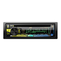
3.1.4 Removing the front chassis assembly
(See Figs.7 and 8)
• Prior to performing the following procedure, remove the front
panel assembly, heat sink and top chassis assembly.
(1) From the both sides of the top chassis assembly, remove
the two screws F attaching the front chassis assembly.
(2) Remove the front chassis assembly from the top chassis
assembly.
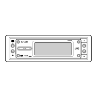
Fig.7
Fig.8
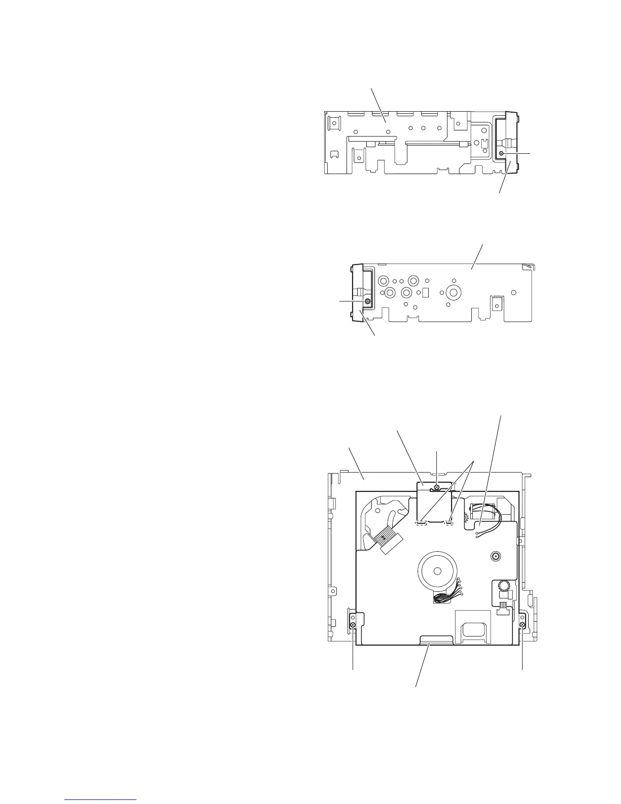
3.1.5 Removing the CD mechanism assembly
(See Fig.9)
• Prior to performing the following procedures, remove the front
panel assembly, heat sink and top chassis assembly.
Reference:
Remove the front chassis assembly as required.
(1) From the inside of the top chassis assembly, remove the
three screws G attaching the CD mechanism assembly.
(2) Release the mecha heat sink from the joints a on the mech-
anism control board and remove the heat sink from the
main body.
(3) Take out the CD mechanism assembly from the top chas-
sis.
Fig.9
Top chassis assembly
Front chassis assembly
F
Top chassis assembly
Front chassis assembly
F
Top chassis
Mecha heat sink
G
G G
CD mechanism assembly
a
Mechanism control board
 Loading...