MX-K3
1-20
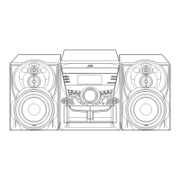
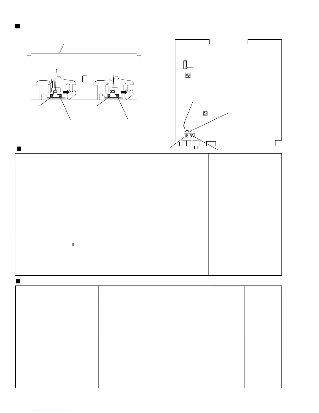
Arrangement of adjusting positions
Items
Measurement
conditions
Measurement method
Standard
values
Adjusting
positions
Tape recorder section
Tuner section
Cassette deck mechanism
(Front side)
Head azimuth screw
(Forward side)
PB Head
(Deck-A)
REC/PB Head
(Deck-B)
T1
L2
Main board Ass'y
CN308
L301
8-Pin
Head screw Head screw
Head azimuth screw
(Forward side)
1. Playback the test tape VT703 (10KHz) or equivalent.
2. Adjust the head azimuth screw to obtain maximum
output and both output of L / R is in 3dB.
3. Put on the screw lock paint after alignments.
1. Insert the recording tape in deck-B.
2. Starting the recording.
3. Adjust the oscillation frequency to 80KHz+/-3KHz by
core of Oscillation coil of L301.
Test tape
: VT703 (10kHz)
Measurement output
terminal
: Left and Right
speaker output
(6-ohm loaded)
or
Headphone Output
(32-ohm loaded)
Recording tape
: TYPE AC-514
Measurement output
terminal
: Erase head terminal
(CN308 8-Pin)
Maximum output
80kHz+/-3kHz
Head azimuth
screw
Adjust the head
azimuth screw only
when the head has
been changed.
Bias coil: L301
Use the High-
Impedance Probe for
Frequency counter
input.
Cassette Head
Azimuth Alignments
Recording Bias
Frequency Alignment
Items
Measurement
conditions
Measurement method
Standard
values
Adjusting
positions
OSC coil adjustment
1.Set the Signal Generator signal to 530KHz the feed to
Loop Antenna.
2.Receiving the signal and the adjust the OSC coil (L2)
obtain the V.T is 1.40V +/-0.05V.
Antenna coil check or adjustment
1.Change the receiving frequency to 603KHz.
2.Adjust the Antenna coil ( L2 ) obtain maximum sensitivity.
(Adjust the SSG output to out of AGC range.)
1. Set the receiving frequency to 531KHz.
2. Feed the 450KHz signal to AM IF input.
3.Adjust the IFT Block T1 obtain to maximum output.
(Adjust the SSG output to out of AGC range.)
Input signal
: 530kHz
Measurement point
: Resistor R3 (AM)
Resistor R6 (FM)
Input signal
: 603kHz
Input signal
: 531kHz
V.T
: 1.40V+/-0.05V
Maximum
sensitivity
Maximum output
OSC/Antenna coil
: L2
Adjust the OSC coil
only when the AM coil
block has been
changed.
IFT (T1)
Adjust the IFT only
when the IFT block has
been changed.
AM Tracking
Alignments
AM IFT Alignments
Note: The adjustment of CD section is not required.
FM VT voltage
measurement point
R3
R6
AM VT voltage
measurement point
Antenna coil
OSC coil

 Loading...