1-6 (No.YD125<Rev.001>)
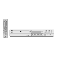
3.5 Removing the REG/SD board (See Figure 6)
• Remove the top cover, front panel assembly and HDD.
(1) Pull out the each wire from the connectors CN5306
,
CN5001
, CN5303, CN801 and CN5305 on the REG/SD
board.
(2) Pull out the socket wires from the connectors CN2102
,
CN5501
and CN4002 on the BE-DIGITAL board.
(3) Remove the five screws E attaching the REG/SD board,
and then remove the REG/SD board.
Fig.6
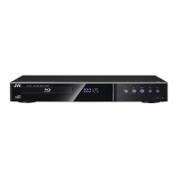
3.6 Removing the BE-DIGITAL board (See Figure 7 and
Figure 8)
• Remove the top cover, HDD and BD drive unit.
(1) Pull out the each wire from the connectors CN1501
,
CN1502
, CN4001, CN2102, CN5501, CN4002 and
CN2801
on the BE-DIGITAL board.
Fig.7
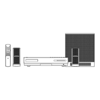
(2) Remove the two screws F attaching the terminal from back
of the main unit.
Fig.8
(3) Remove the four screws G attaching the BE-DIGITAL
board.
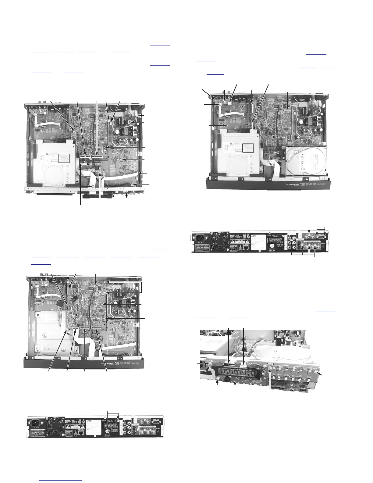
3.7 Removing the D-SUB/BNC board and TERMINAL board
(See Figure 9 and Figure 10)
• Remove the top cover.
(1) Pull out the socket wires from the connectors CN1501
and
CN1502
on the BE-DIGITAL board.
(2) Pull out the each wire from the connectors CN401
, CN402
and CN403 on the D-SUB/BNC board.
Fig.9
(3) Remove the five screws H and the two nuts attaching the
each terminal from back of the main unit.
Fig.10
3.8 Removing the DISPLAY board (See Figure 11)
• Remove the top cover and front panel assembly.
(1) Remove the three screws J attaching the DISPLAY board.
(2) Pull out the each wire from the connectors CN7401
,
CN7402
and CN7403 on the DISPLAY board.
Fig.11
E
CN5305
CN801
CN5306
CN4002
REG/SD
Board
E
E
CN5001
CN5303ECN2102
BE-DIGITAL
Board CN5501
CN4001
G
G
G
CN1502 CN1501 CN2801
CN2102 CN5501
CN4002
BE-DIGITAL
Board
F
CN401
CN402
CN403
CN1501
CN1502
BE-DIGITAL Board
D-SUB/BNC
Board
TERMINAL
Board
H
H
Nut
J
J
J
CN7403
CN7401 CN7402
DISPLAY Board

 Loading...