z
0
C.J7
__,_
--.,J
0)
0)
__,_
I
<.,.)
4
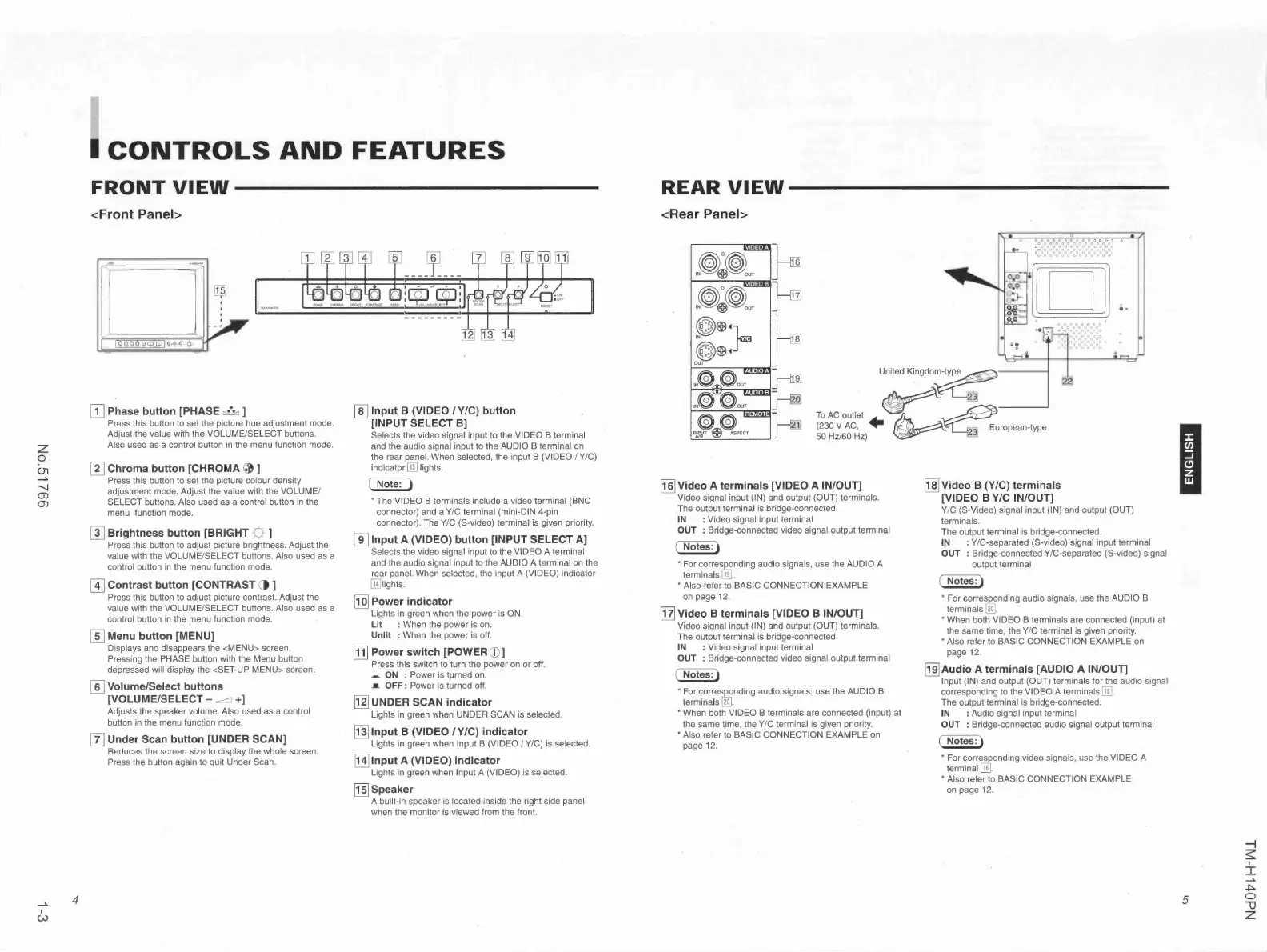
CONTROLS AND FEATURES
FRONT VIEW-------------
<Front Panel>
[Il Phase button [PHASE r::lli ]
Press this button to set the picture hue adjustment mode.
Adjust the value with the VOLUME/SELECT buttons.
Also used as a control button in the menu function mode.
~
Chroma button [CHROMA
~
]
Press this button to set the picture colour density
adjustment mode. Adjust the value with the VOLUME/
SELECT buttons. Also used as a control button in the
menu function mode.
[!] Brightness button [BRIGHT
◊
]
Press this button to adjust picture brightness. Adjust the
value with the VOLUME/SELECT buttons. Also used as a
control button in the menu function mode.
[!J Contrast button [CONTRAST () ]
Press this button to adjust picture contrast. Adjust the
value with the VOLUME/SELECT buttons. Also used as a
control button in the menu function mode.
[ID Menu button [MENU]
Displays and disappears the <MENU> screen.
Pressing the PHASE button with the Menu button
depressed will display the <SET-UP MENU> screen.
[!] Volume/Select buttons
[VOLUME/SELECT - ..cc::::J +]
Adjusts the speaker volume. Also used as a control
button in the menu function mode.
[zJ Under Scan button [UNDER SCAN]
Reduces the screen size to display the whole screen.
Press the button again to quit Under Scan.
[ID Input B (VIDEO /Y/C) button
[INPUT SELECT B]
Selects the video signal input to the VIDEO B terminal
and the audio signal input to the AUDIO B terminal on
the rear panel. When selected, the input B (VIDEO /Y/C)
indicator [ill lights.
~
• The VIDEO B terminals include a video terminal (BNC
connector) and a V/C terminal (mini-DIN 4-pin
connector). The V/C (S-video) terminal is given priority.
[]J Input A (VIDEO) button [INPUT SELECT A]
Selects the video signal input to the VIDEO A terminal
and the audio signal input to the AUDIO A terminal on the
rear panel. When selected, the input A (VIDEO) indicator
[ill lights.
[IQ] Power indicator
Lights in green when the power is ON.
Lit : When the power is on.
Unlit : When the power is off.
[TI] Power switch [POWER CD]
Press this switch to turn the power on or off.
- ON : Power is turned on.
.a OFF: Power is turned off.
lg] UNDER SCAN indicator
Lights in green when UNDER SCAN is selected .
~
Input B {VIDEO /V/C ) indicator
Lights in green when Input B (VIDEO /V/C) is selected.
IH] Input A {VIDEO) indicator
Lights in green when Input A (VIDEO) is selected .
~ Speaker
A built-in speaker is located inside the right side panel
when the monitor is viewed from the front.
REAR VIEW---------------
<Rear Panel>
United Kingdom-ty~
~ ~ 2:j]
ToACoutlet ~ -
~
(230 V AC, + \fC_'>; ___ • EL European-type
50 Hz/60 Hz) 2"1
~
Video A terminals [VIDEO A IN/OUT]
Video signal input (IN) and output (OUT) terminals .
The output terminal is bridge-connected .
IN : Video signal input terminal
OUT : Bridge-connected video signal output terminal
( Notes:)
• For corresponding audio signals, use the AUDIO A
terminals [ill.
• Also refer to BASIC CONNECT ION EXAMPLE
on page 12.
ITI] Video B termina ls [VIDEO B IN/OUT]
Video signal input (IN) and output (OUT) terminals.
The output terminal is bridge-connected.
IN : Video signal input terminal
OUT : Bridge-connected video signal output terminal
( Notes:)
• For corresponding audio signals, use the AUDIO B
termina ls rm.
• When both VIDEO B terminals are connected (input) at
the same time, the Y/C terminal is given priority.
• Also refer to BASIC CONNECTION EXAMPLE on
page 12.
[ID Video B (Y /C) terminals
[VIDEO B Y/C IN/OUT]
V/C (S-Video) signal input (IN) and output (OUT)
terminals.
The output terminal is bridge-connected.
IN : VIC-separated (S-video) signal input terminal
OUT : Bridge-connected VIC-separated (S-video) signal
output termina l
( Notes:)
• For corresponding audio signals, use the AUDIO B
terminals rm.
• When both VIDEO B terminals are connected (input) at
the same time, the V/C terminal is given priority.
• Also refer to BASIC CONNECTION EXAMPLE on
page 12.
~ Audio A terminals [AUDIO A IN/OUT]
Input (IN) and output (OUT) termina ls for the audio signal
corresponding to the VIDEO A terminals [ill.
The output termina l is bridge-connected.
IN : Audio signal input terminal
OUT : Bridge-connected audio signal output terminal
( Notes:)
• For corre~onding video signals, use the VIDEO A
terminal llij.
• Also refer to BASIC CONNECTION EXAMPLE
on page 12.
I
5
-,
~
I
I
+::>
0
-0
z
 Loading...