EasyManua.ls Logo

Kärcher HD 5 12 User Manual

Kärcher HD 5 12
12 pages
To Previous Page IconTo Previous Page
Page #12 background imageLoading...
Page #12 background image
New Unit Information 02.2004
Technical specifications HD 5/12
Page 12 / 12
The technical data sheet and the circuit diagram will be included in the next issue of the spare parts
CD-ROM (DISIS) and are available in the Intranet.
Technical data sheet: Folder: „Central / Service Info Int’l / Technical Specifications“
Circuit diagram: Folder: „Central / Service Info Int’l / Circuit Diagram“
If required, the operating instructions and the spare parts lists can be ordered as a paper copy from
the spare parts service by quoting the relevant part number.
Special tool
Assembly tool (12mm) for high-pressure and oil seals 2.901-036
Tightening torque
Cylinder head bolt 23-27 Nm
Swash plate 12-15 Nm
Technical specifications
Unit Type Unit No. Circuit
diagram
Operating
instructions
Maintenance
booklet
Spare parts
list
HD 5/12
(220-240 Volt / 50 Hz)
1.514-101 0.087-853 5.960-966 5.950-582 5.970-209
Question and Answer IconNeed help?

Do you have a question about the Kärcher HD 5 12 and is the answer not in the manual?

Kärcher HD 5 12 Specifications

General IconGeneral
Flow Rate500 l/h
Max Water Flow500 l/h
Voltage230 V
Frequency50 Hz
Pressure120 bar

Summary

Technical Features

Drive Unit and Pump Specifications

Details the motor type, pump configuration, and materials used.

Electrical and Cleaning Agent Systems

Covers electrical components and the cleaning agent metering system.

Standard Accessories

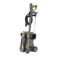
Lists the included accessories like the spray gun and nozzle.

Front View Component Identification

External Parts - Front

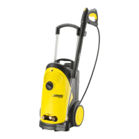
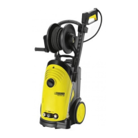
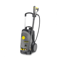
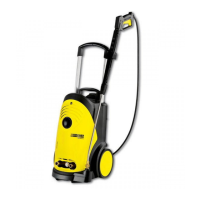
Labels the external components visible from the front of the unit.

Rear View Component Identification

External Parts - Rear

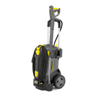
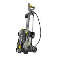
Labels the external components visible from the rear of the unit.

Internal Components - Front View

Components with Front Cover Removed

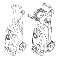
Identifies internal parts like the electrical box and pump after cover removal.

Electrical Box Details

Electrical Box Components and Access

Details the electrical box, unit switch, capacitor, and opening procedure.

Rear Cover Access and Components

Rear Cover Removal and Repair Note

Explains how to remove the rear cover and a note on clip repair.

Bottom View Component Identification

Components Visible From Below

Labels components such as the high-pressure connection and water inlet.

Motor and Pump Assembly

Detailed Motor and Pump Breakdown

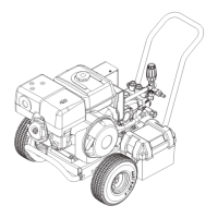
Provides a diagram and list of all motor and pump internal parts.

Cylinder Head Assembly

Detailed Cylinder Head Breakdown

Illustrates the cylinder head with its valves, pistons, and connections.

Troubleshooting Common Issues

Fault Diagnosis and Solutions

Lists common unit faults and provides step-by-step solutions.

Technical Specifications and Maintenance Data

Unit Specifications and Document References

Includes unit number, circuit diagram, and document references.

Special Tools and Tightening Torques

Lists specialized tools and critical torque values for assembly.

Related product manuals