26
GB
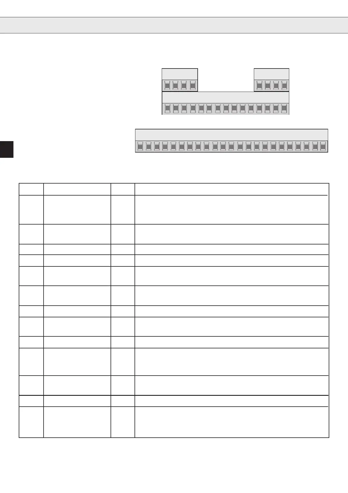
1. Installation and Connection
123456789101112
13 14 15 16 17 18 19 20 21 22 23
20 22 23
1234
21
16 17 1856789101112131415 19
1.1.1Assignment of
Terminal Strip X1
1.1. Control circuit
Version C
PIN Function Name Description
X1.1 NO contact RLA Relay output
X1.2 Opening contact RLB Function see parameter CP.22
X1.3 Switching contact RLC ( factory setting: fault indication)
X1.4 Fixed frequency 1 I1 X1.4 + X1.5 = fixed frequency 3
X1.5 Fixed frequency 2 I2 no input = analog set value
X1.6 DC-braking I3 activates the dc-braking
X1.7 Energy saving funct. I4 Output voltage is reduced to 70%
X1.8 REF+ REF+ Difference voltage; Voltage difference is added to/
X1.9 REF- REF- subtracted from inputREF (X1.17)
X1.10 Forward F Preset rotation; forward has priority
X1.11 Reverse R
X1.12 Frequency depend. OUT1 Transistor output switches at switch f
real
= f
set
X1.13 Digital Mass 0V Potential for digital in-/outputs
X1.14 15V +15V voltage supply for digital in-/outputs (max.100mA)
X1.15 Analog output AOUT Analog output of the real frequency 0...10VDC = 0...100Hz
X1.16 +10V CRF Supply voltage for set value potentiometer (max. 4 mA)
X1.17 Set value input REF Factory setting 0...10V (0...20 and 4...20mA adjustable with CP.24)
X1.18 Common COM Mass for analog in- and outputs
X1.19 Control release ST Power modules are triggered; if opening in case of error
Reset; if opening during operation, the motor costs.
X1.20 Reset RST Hardware reset; only possible when an error occurs
X1.21 NO contact FLA Relay output; switches,when level
X1.22 Opening contact FLB from parameter CP.23 is reached
X1.23 Switching contact FLC (frequency dependent switch)
Artisan Technology Group - Quality Instrumentation ... Guaranteed | (888) 88-SOURCE | www.artisantg.com
 Loading...


