28
GB
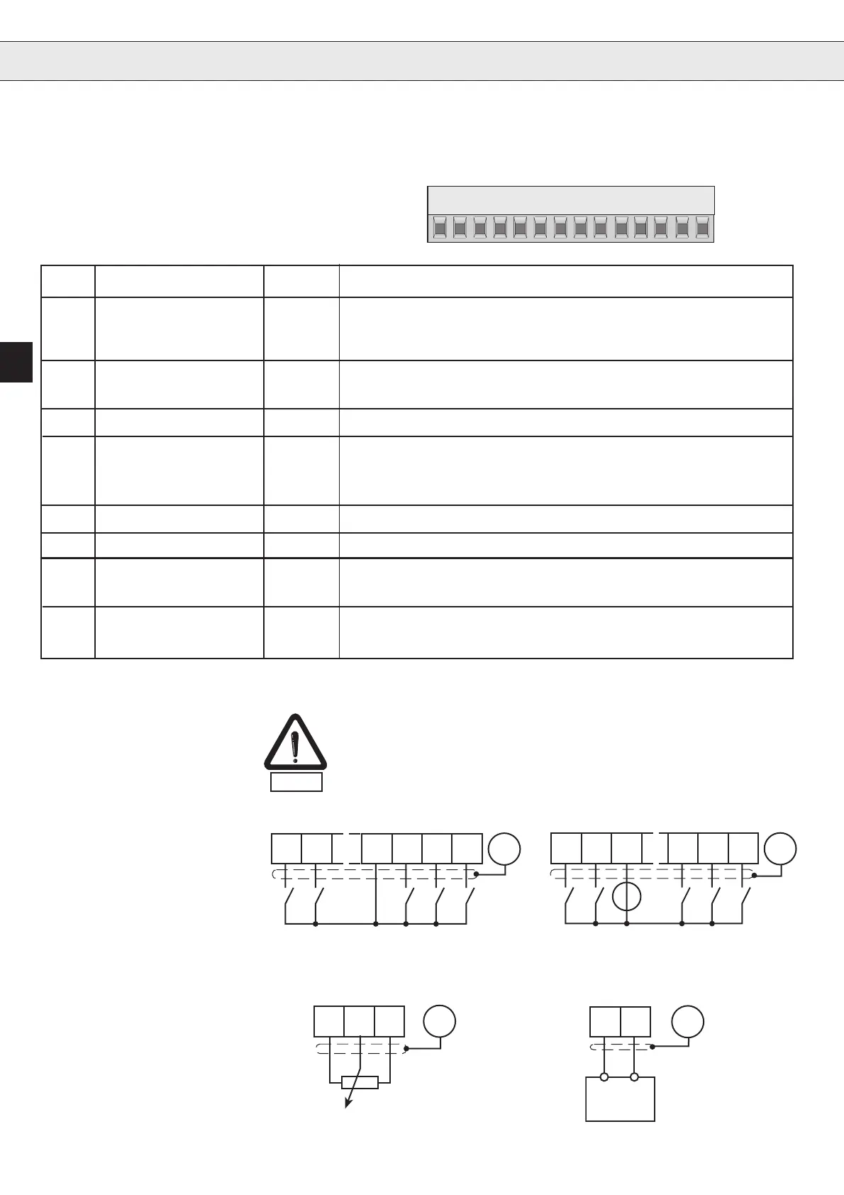
Installation and Connection
123456789101112
13 14
PIN Function Name Description
X1.1 NO contact RLA Relay output
X1.2 Opening contact RLB Function see parameter CP.22
X1.3 Switching contact RLC ( factory setting: fault indication)
X1.4 Fixed frequency 1 I1 X1.4 + X1.5 = fixed frequency 3
X1.5 Fixed frequency 2 I2 no input = analog set value
X1.6 Digital Mass 0V Potential for digital in-/outputs
X1.7 +10V CRF Supply voltage for set value potentiometer (max. 4mA)
X1.8 Set value input REF 0...10VDC for analog set value
X1.9 Common COM Mass for analog in- and outputs
X1.10 Analog output AOUT Analog output of real frequency 0...10VDC = 0...100Hz
X1.11 15V +15V voltage supply for digital in-/outputs (max. 100mA)
X1.12 Reverse R Preset rotation; forward has priority
X1.13 Forward F
X1.14 Control release ST/RST Power modules are triggered; if opening in case of error
Reset; if opening during operation, the motor costs.
In order to prevent a malfunction caused by interference voltage supply
on the control inputs, the following directions should be observed:
- Use shielded/drilled cables
- Lay shield on one side of the inverter onto earth potential
- Lay control and power cable separately (about 10...20 cm apart)
- Lay crossings in a right angle (in case it cannot be prevented)
1.2.2Connection of the
control
EMC
1.2.3 Digital inputs
4 5 11 12 13 14
PE
4 6 12 13 14
PE
+
5
13...30VDC
External voltage supply
Internal voltage supply
Internal analog set-point
setting 0...10V
External analog
set-point setting
1.2.4 Analog inputs
789 PE
89
+-
SPS
PE
R = 3...10 kΩ
0...10 DCV
Ri = 4 kΩ
1.2 Control circuit
Version S
1.2.1 Assignment of
Terminal Strip X1
Artisan Technology Group - Quality Instrumentation ... Guaranteed | (888) 88-SOURCE | www.artisantg.com
 Loading...


