GB-20
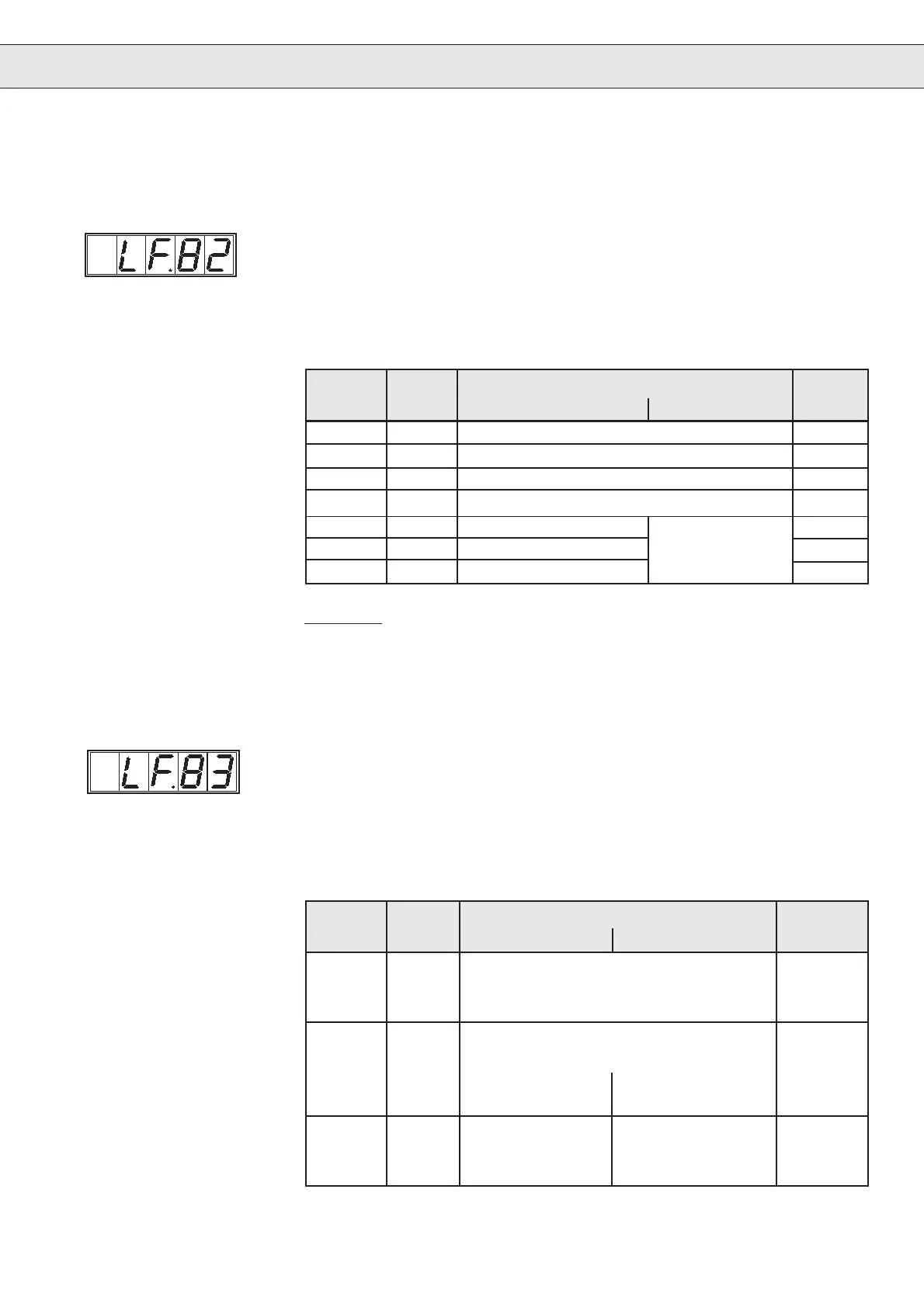
X2 Output State
Terminal X2 (upper terminal)
With the X.2 output state it can be easily checked, whether the outputs
were set by the inverter control. Every digital output has a specific
value. If several outputs are set at the same time, the sum of the values
is shown.
Value table:
Operating Parameter
Terminal X2 (upper terminal)
With the X.2 input state it can be easily checked, whether the input
signals reached the inverter control. Every input (output) has a specific
value. If several inputs are set, the sum of the values is shown.
Value Table:
X2 Input State
Example: Input control release (X2.1) and direction forward (X2.3) are
triggered with 24V .
Display value: 1+4 = 5
4. Operating Parameter
Display Valency Function Output
Combivis > G D + E terminal
O1 1 digital X2.8
output signal:
braking control
O2 2 digital X2.9
output signal:
main contactor main contactor
control inverted control
O3 4 relay relay ready-to-operate X2.20/X2.22
control cabinet fan collective fault
overspeed
Display Valency Function Input
Combivis > G D + E terminal
ST 1 control release X2.1
RST 2 Reset X2.2
F 4 direction of travel forward X2.3
R 8 direction of travel reverse X2.4
I1 16 control mode X2.5
I2 32 door drive active setpoint selection X2.6
I3 64 door drive setpoint setting binary-coded X2.7

 Loading...