GB-8
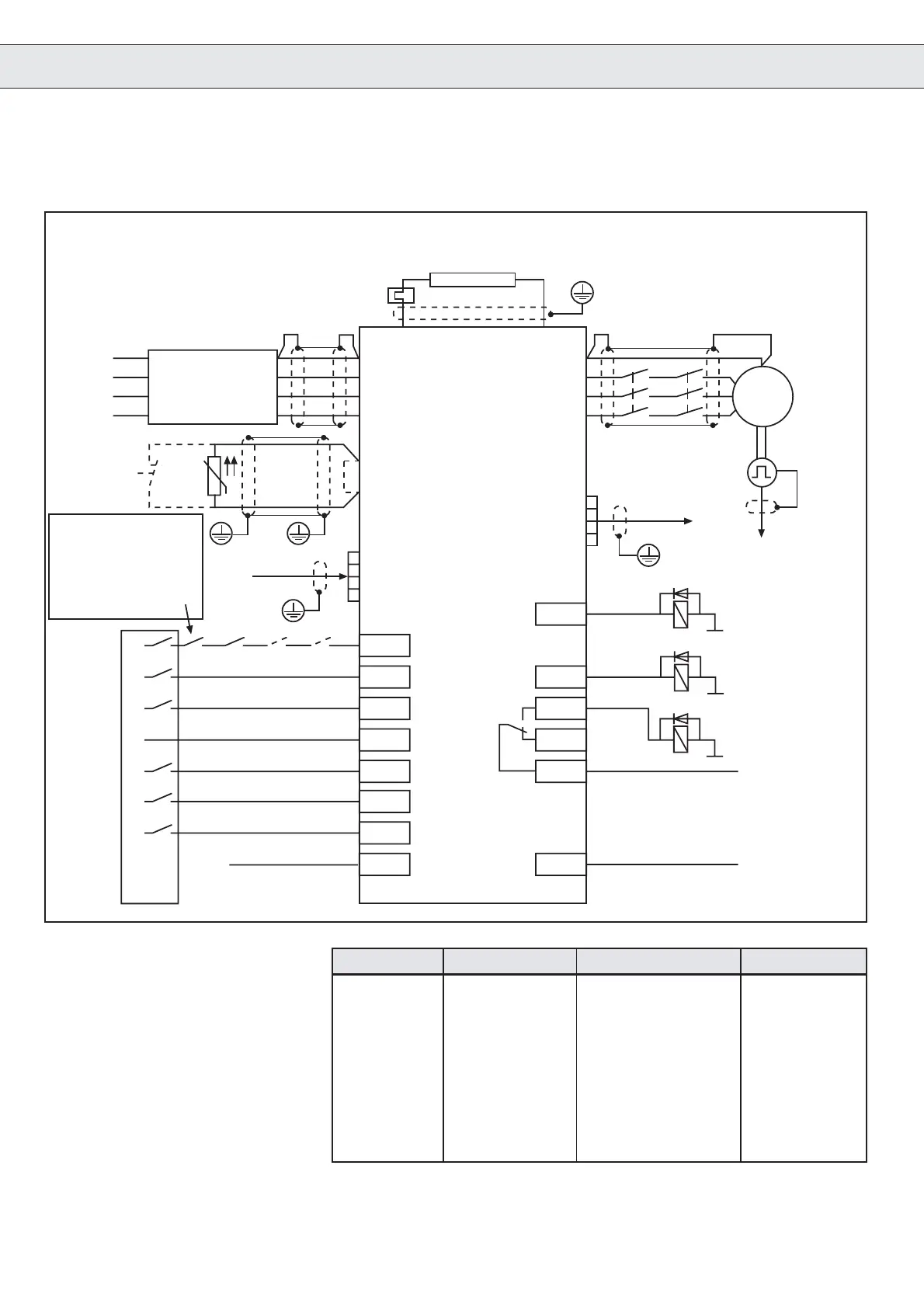
2.2 Example connection diagram for Lift Inverters in D- and E-housing
Connection
M
3 ~
X2.1
X2.2
X2.3
X2.4
X2.5
X2.6
X2.7
X2.23
X2.8
X2.9
X2.20
X2.21
X2.22
X2.11
Braking resistor
PA
PB
PE
U
V
W
PE
L1
L2
L3
EMC-Filter
M
A
I
N
S
K
1
K
2
Encoder
X4
to the lift
control
OH
OH
ϑ
Motor-
PTC
ϑ
Encoder
X4 (15-pole)
X5 (9-pole)
KEB F4-F
Lift
K
BR
Braking
control
Main con-
tactor control
K
11
+24V
Ground GND
*
*
Direction of travel forward
Direction of travel reverse
Control release
K
12
L
I
F
T
-
C
O
N
T
R
O
L
K
11
K
1
K
2
RST
Setpoint selection
binary-coded
Setpoint selection
binary-coded
Setpoint selection
binary-coded
+24V
To switch off the control
release the auxiliary
contacts of both main
contactors or a relay (K
12
),
behind the safety circuit,
must be used.
K
Ready
*
* All 24 V relays controlled by the frequency
inverter must have diode are suppression.
X2.5 X2.6 X2.7
V = 0 0 0 0
V
B
100
V
E
010
V
N
110
V
I
001
V
1
101
V
2
011
n
Door
111

 Loading...
