ANTRIEBSTECHNIK
GB 17
GB
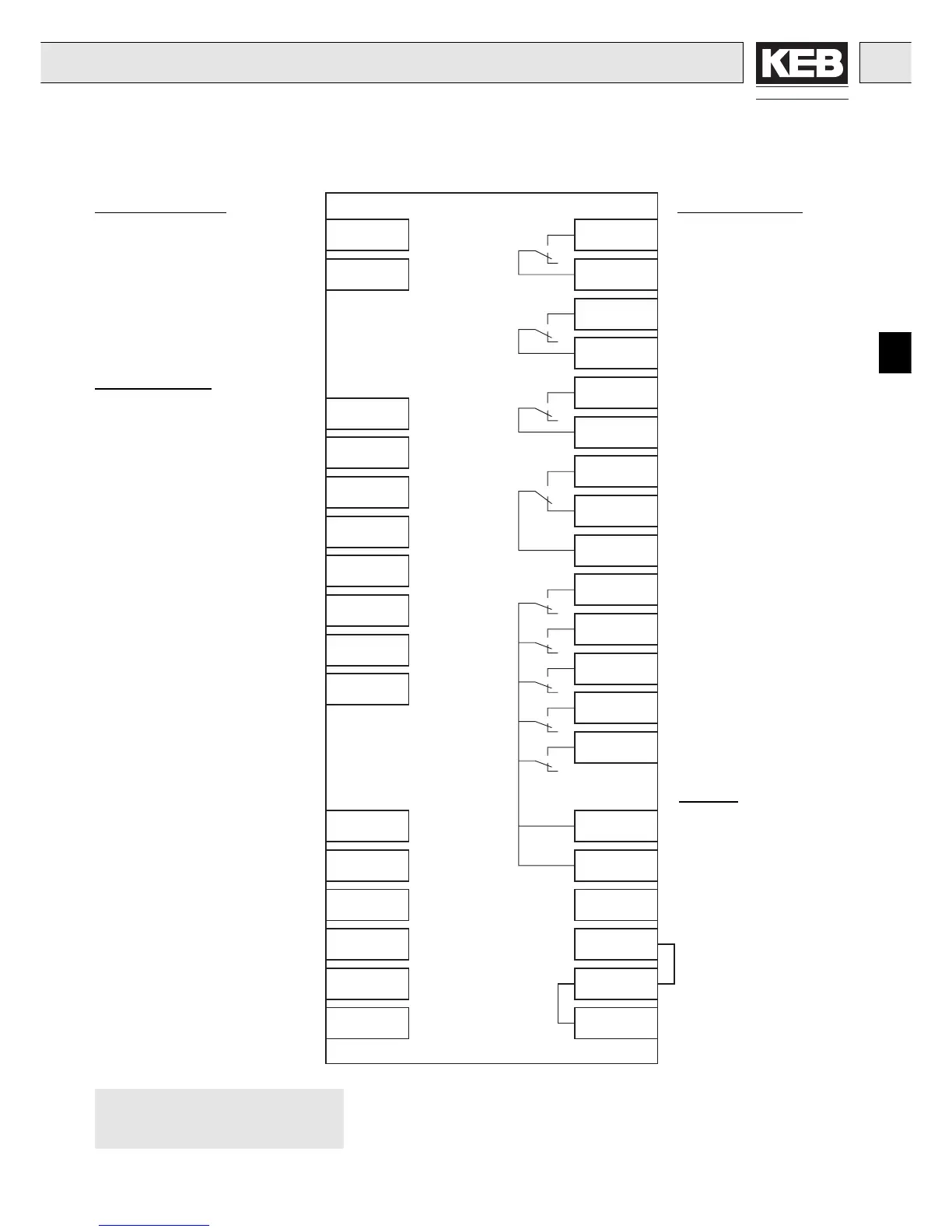
6. Connection
6.1 Wiring Diagram: Control Terminal X2 and I/O-Expander X3
X2.8
Braking control
Deceleration control
Positioning speed
Main contactor control
Relay contact
DC-monitoring
Operating frequency warning
Digital Outputs:
Control release
Direction of travel reverse
Contactor control
Reset
Direction of travel foward
Digital Inputs:
Re-levelling, V
B
Inspection speed, V
I
Inspection speed 1, V
1
Inspection speed 2, V
2
Positioning, V
E
Rated max. speed, V
N
Setpoint selection
(only with LF.2 = 2)
Supply
With binary coded setpoint selection
(LF.2 = 1), terminal assignment see
page GB 25 - GB 26
X2.9
X2.1
X2.2
X2.3
X2.4
X2.5
X2.6
X2.7
X3.1
X3.2
X3.3
X3.4
X3.5
X3.6
X3.7
Secondary drive setpoint input
Control mode
Secondary drive active
Braking control
Main contactor control inverted
X3.15
X3.16
X3.18
X3.19
Relay contact
Ready
X3.20
X3.21
X2.20
X2.21
X2.22
X3.13
X3.14
X3.17
X3.22
X3.23
Relay contact
Heat sink temperature > LF.66
(5 K hysteresis)
Heat sink temperature < LF.66
Relay contact
Motor temperature warning
X3.9
X3.10
X2.23
X2.11
X3.11
X3.12
Ground (GND)
Ground (GND)
+24V (control card)
+24V (I/O-card)
+24V (I/O-card)
Ground (GND)
Relay Outputs:

 Loading...
