GB 10
GB
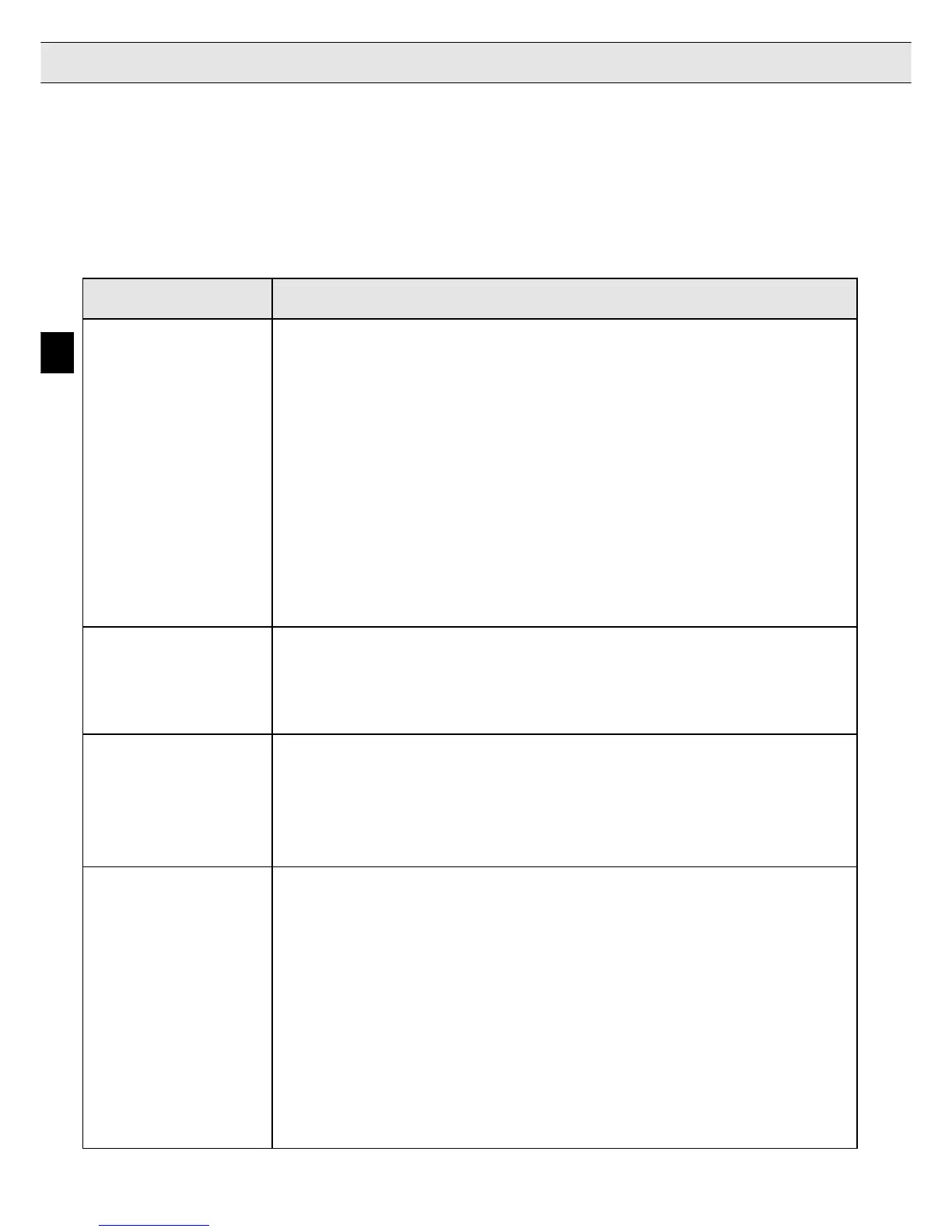
3.4 Function of the Digital Outputs / Relay Outputs
After the voltage is switched on several digital outputs need approximately 2s for initialization. All
switching thresholds have 12% hysteresis, exept for output X3.22 which has 6%.
Exception: Output X3.22 has 6% hysteresis.
Terminal Description
X2.8
Braking
The output is activated when the following conditions are met:
Control
- no error message is present
- a setpoint must be selected (V
X
≠ 0 m/s)
- the contactor control input (X3.1) must be set
- the control release (X2.1) must be activated
- a direction of travel (X2.3/X2.4) must be selected
- a motor current must flow (hardware test);
The output is reset when one of the following conditions is met:
- overspeed is recognized
- a fault signal occurs
- after the setpoint values are removed the operating point of the brake
(LF.60) is gone below
- 5 s after the setpoint values are removed
X2.9
Main Contactor
The output signal corresponds to the inverted signal of terminal X3.20.
Control
When the function of the contactor control is not used, input X3.1 must be
inverted
bridged with output X2.9, to simulate the contactor control.
X2.20
Relay
How the relay output is switched depends on the temperature level set
X2.21
Control Cabinet
(parameter LF.66).
X2.22
Fan Control
actual heat sink temperature > LF.66 Relay releases
actual heat sink temperature < LF.66 - 5 K Relay picks up
! see wiring diagram page GB 17 !
X3.13
Ready for
The output is set, after the inverter has completed an internal check (after
Operation
the voltage is switched on). The output is reset, when the supply voltage is
Common Error
switched off, when an inverter disturbance occurs or when overspeed is de-
Overspeed
tected.
Note: The overspeed detection only works when the encoder is
connected, the speed controller (LF.30 ≠ 0 ) is switched on and
a valid speed is selected. When overspeed is reached the
inverter stops and the error message "E.OS" (Error, overspeed)
is shown. The outputs for contactor control and braking are reset.
3. Inputs/Outputs

 Loading...
