GB - 15
Installation and Connection
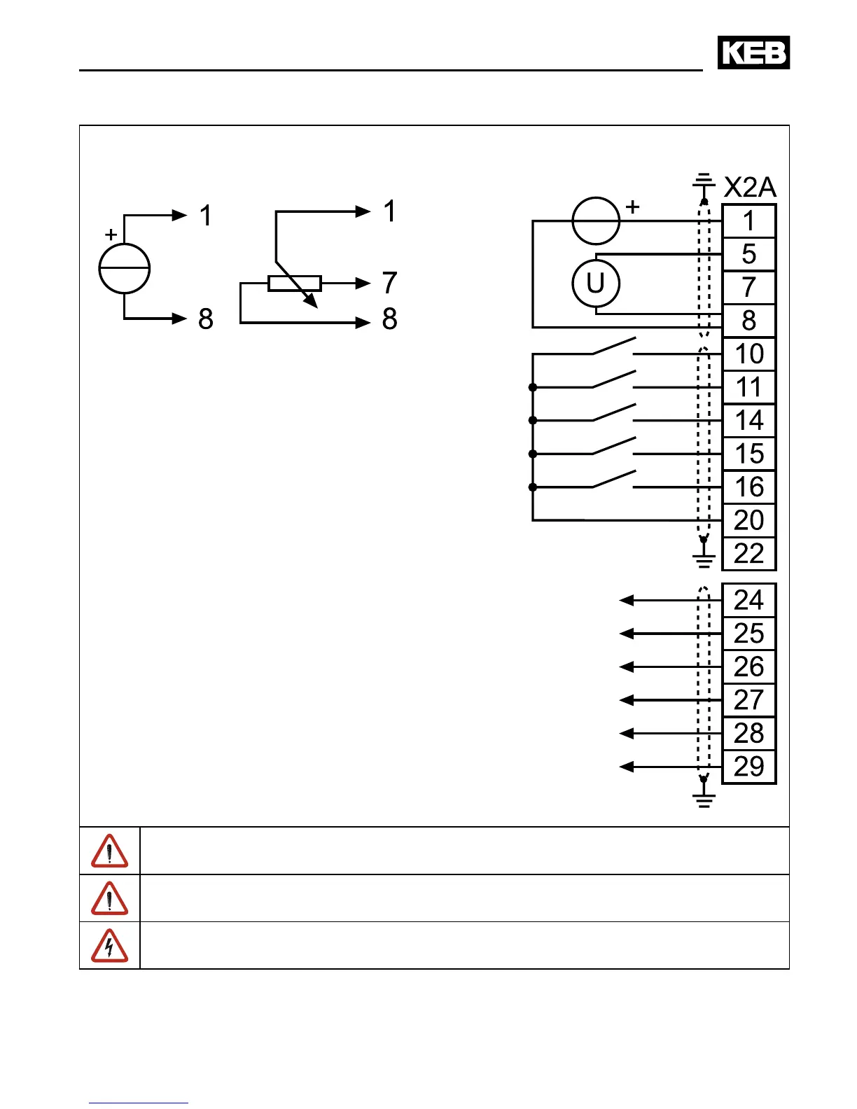
3.4.2 Connection of the control terminal strip
Setpoint signal
0…±10 V DC
max. 30 V DC / 0.01…1 A
Current signal
0…±20 mA
4…20 mA
not at housing A
and B
Setpoint potentiometer
3…10 kΩ
Analog output
±10 V DC
max. 5 mA
max. 30 V DC / 0.01…1 A
To avoid interferences a separate shielding must be provided for analog and digital control
lines. Depending on the use of the relay outputs, an extra shielding is to be used, too.
In case of inductive load on the relay outputs a protective wiring must be provided (e.g.
free-wheeling diode)!
The terminals of the control terminal strip and the transmitter inputs are securely isolated
in accordance with EN 50178.
 Loading...


