EasyManuals Logo
Home>KEB>DC Drives>COMBIVERT F5 Series

KEB COMBIVERT F5 Series Installation Manual

KEB COMBIVERT F5 Series
46 pages
To Next Page IconTo Next Page
To Previous Page IconTo Previous Page
Page #21 background imageLoading...
Page #21 background image
GB - 20
*)
X2
1
2
3
4
5
6
7
8
9
10
11
12
13
14
15
16
17
18
19
20
21
22
23
24
25
26
27
28
29
Setpoint potentiometer
3…10 kΩ
Setpoint signal
0…±10 V DC
Analog output
±10 V DC /
max. 5 mA
Installation and Connection
3.6.2 Connection of the control terminal strip
max. 30 V DC / 0.01…1 A
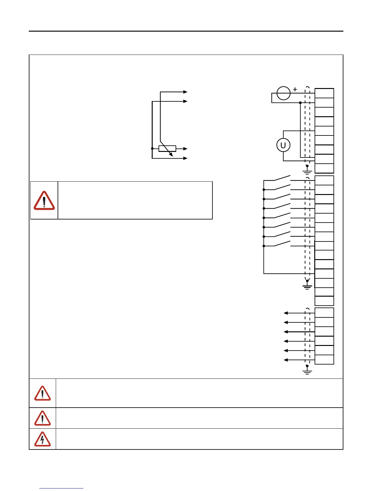
*) Connect potential equalizing line only if a
potential difference of >30 V exists between
the controls. The internal resistance is red-
uced to 30 kΩ.
To avoid interferences a separate shielding must be provided for analog and digital
control lines. Depending on the use of the relay outputs, an extra shielding is to be
used, too.
In case of inductive load on the relay outputs a protective wiring must be provided (e.g.
free-wheeling diode)!
The terminals of the control terminal strip and the transmitter inputs are securely isola-
ted in accordance with EN 50178.

Table of Contents

Other manuals for KEB COMBIVERT F5 Series

Questions and Answers:

Question and Answer IconNeed help?

Do you have a question about the KEB COMBIVERT F5 Series and is the answer not in the manual?

KEB COMBIVERT F5 Series Specifications

General IconGeneral
BrandKEB
ModelCOMBIVERT F5 Series
CategoryDC Drives
LanguageEnglish

Related product manuals