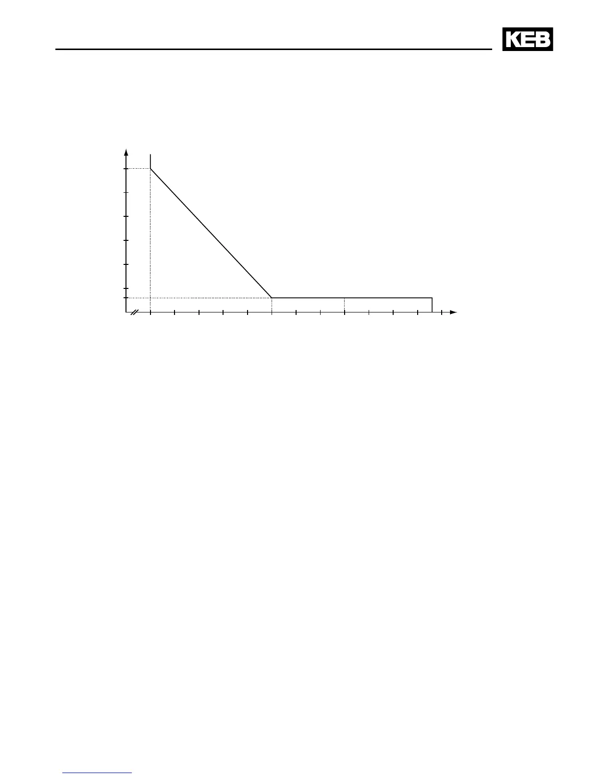
Load [%]
On exceeding a load of 105% the overload integrator starts. When falling below the inte-
grator counts backwards. Error E.OL is triggered if the integrator achieves the overload
characteristic.
A.2 Calculation of the motor voltage
The motor voltage for dimensioning of the drive is depending on the used components. The
mains voltage reduces according to the following table:
Mains choke Uk 4 % Example:
Inverter open loop 4 % Closed loop inverter with mains- and motor choke at
non-rigid supply system:
400 V mains voltage - 15 % = 340 V motor voltage
Inverter closed loop 8 %
Motor choke Uk 1 %
Non-rigid supply system 2 %
A.3 Maintenance
All work may only be done by qualied personnel. The security must be ensured as fol-
lows:
• Disconnect power supply at MCCB
• Secure against restarting
• Await discharge time of capacitors (if necessary controlling by measurement at „+PA“
and „-“, respectively “++“ and „--“)
• Ensure loss of voltage by measurement
In order to avoid premature ageing and avoidable malfunctions, the measures mentioned
below must be carried out in the appropriate cycle.
 Loading...


