Installation
©
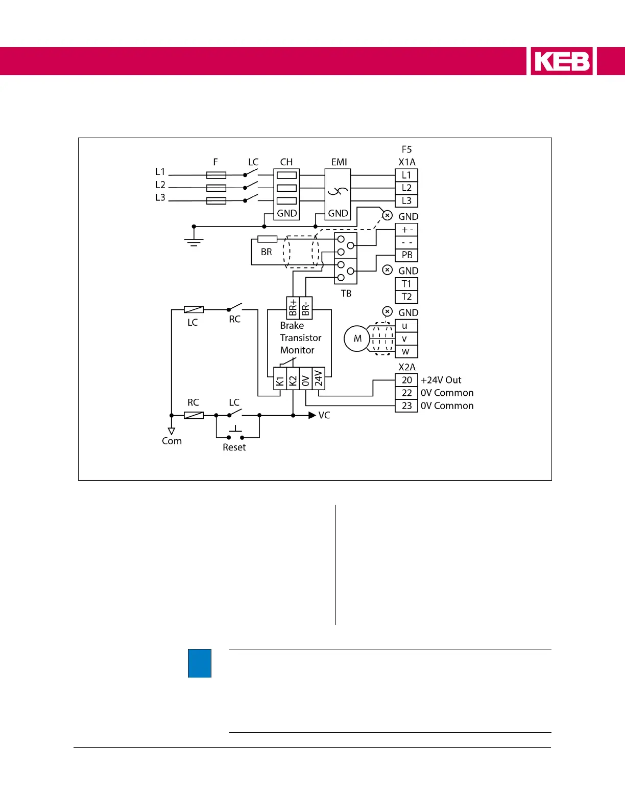
5.2.2.2 AC Line Contactor
Figure 5: Wiring Diagram: AC Contactor
Key
F Branch-Circuit Fuses CH Line Choke
EMI EMI Filter F5 F5 Series AC Drive
TB Distribution / Connection Block BR Brake Resistor
LC Line Contactor RC Reset Relay – Latching Circuit
VC Control Voltage Com Control Voltage Common
i
The terminals on the Drive and the Brake Transistor Monitor are
rated for single conductor only. Two conductors shall not be joined
to one terminal.
To connect the Brake Transistor Monitor, an external distribution
or connection block (TB) must be used to connect the Brake
resistor and the Brake Transistor Monitor in parallel.
 Loading...


