6.7.1 Monitoring braking transistor
General
• The function "monitoring braking transistor" is standard for housing P with braking
option.
• It must be wired according to the wiring diagrams.
• This circuit offers a direct protection in case of a defective braking transistor.
• If the braking transistor is defective, a relay opens the terminals K1 / K2.
• Terminals K1 / K2 are integrated into the holding circuit of the coupling relay for the
input contactor, so the mains voltage is switched off in error case.
• Regenerative operation is also secured by the internal fault disconnection.
• Chapter => Wiring Diagrams contains examples of how to wire the integrated relay
via terminals K1 / K2.
6.7.2 External braking resistor without temperature monitoring
External braking resistors are available for air-cooled and liquid-cooled devices.
ATTENTION
Only "intrinsically safe" braking resistors are permissible for operation
without temperature monitoring.
An intrinsically safe braking resistor will melt internally like a fuse in case of overload
due to overheating. There is no short circuit or earth fault. As a result, the drive con-
verter changes to "Error! Overvoltage" with the next deceleration process (when the
braking resistor is required).
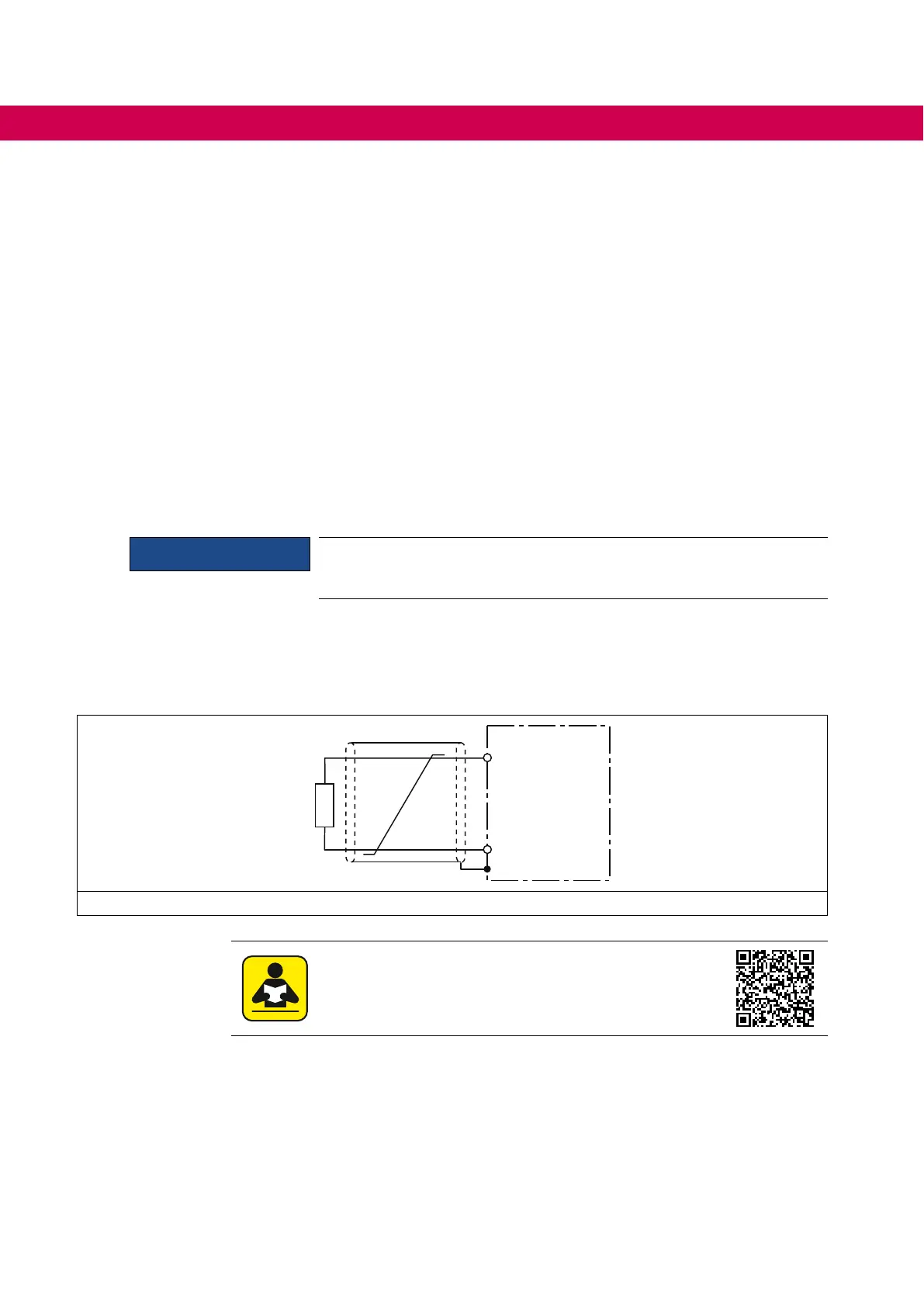
+PA
PB
R
U3
Figure 23: Intrinsically safe braking resistor without temperature monitoring
Technical data and design of intrinsically safe braking
resistors.
https://www.keb.de/leadmin/media/Manuals/dr/ma_dr_safe-braking-re-
sistors-20106652_en.pdf
76
ELECTRICAL INSTALLATION

 Loading...


