4 Displays and operating elements
4.1 Diagnostic display (DIAG)
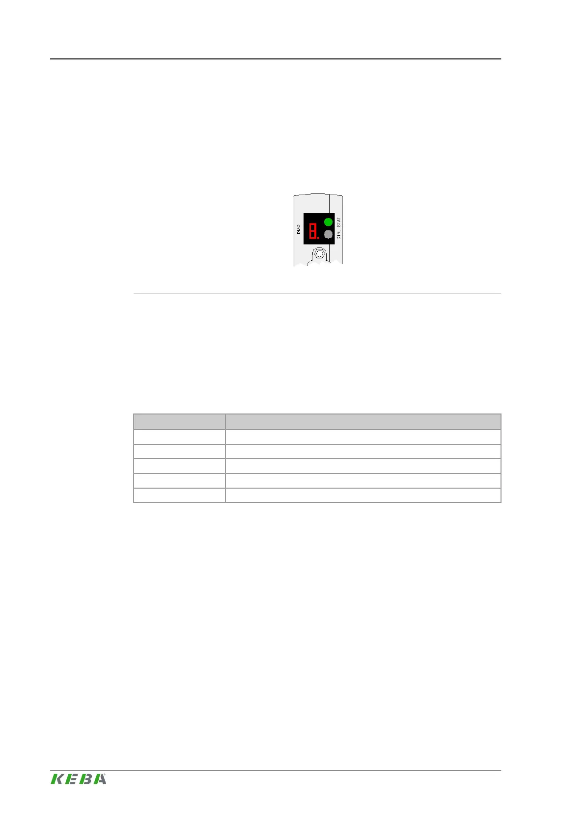
A single-digit 7-segment display on the front side indicates the start-up modes
and error codes.
Fig.4-1: Diagnosis display and CTRL key
Further information: See system manual.
4.2 Status LEDs
The multi-colored status LED on the CPU module is located above the control
key (CTRL).
Display Significance
Dark No supply voltage
Flashing green Initialization phase
Green Operation
Flashing red Error on module (e.g. overload, line interruption, etc.)
Red Fatal module error – the module is out of operation.
4.3 Control key (CTRL)
The control key (CTRL) is located next to the 7-segment-display on the right.
Different functions can be executed with the key, e.g. switching over the control
to a different operating state. For further information see: System manual
4.4 CAN Status LEDs
The module has two CAN Status LEDs (RX- and TX-LEDs) per CAN interface,
which are activated from the Microcontroller.
Displays and operating elements
CP 263/S, CP 263/X
© KEBA 2014
Project engineering manual V1.0118
 Loading...
