Fig.6-6: Connection example for CAN circuit
Information
Both SGND (Signal Ground) and GND (optional ground) connections are
connected internally. The designation was selected to correspond with the
standard CiA (CAN in Automation).
Further information: See system manual.
6.4.2 Cable and plug specification
Further information: See system manual.
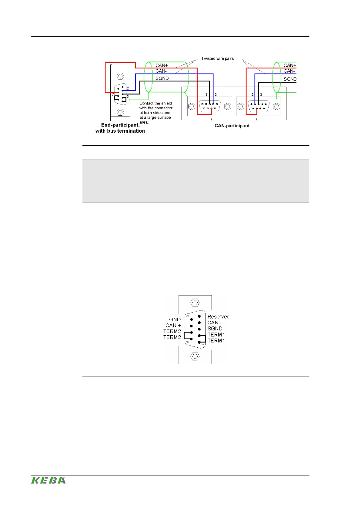
6.4.3 CAN bus termination
To activate the bus termination at the first and last participant, both the pins 4
and 5 (TERM1) must be connected as well as the pins 8 and 9 (TERM2).
Fig.6-7: CAN interface with activated bus termination
Connections and wiring
CP 263/S, CP 263/X
© KEBA 2014
Project engineering manual V1.0128
 Loading...
