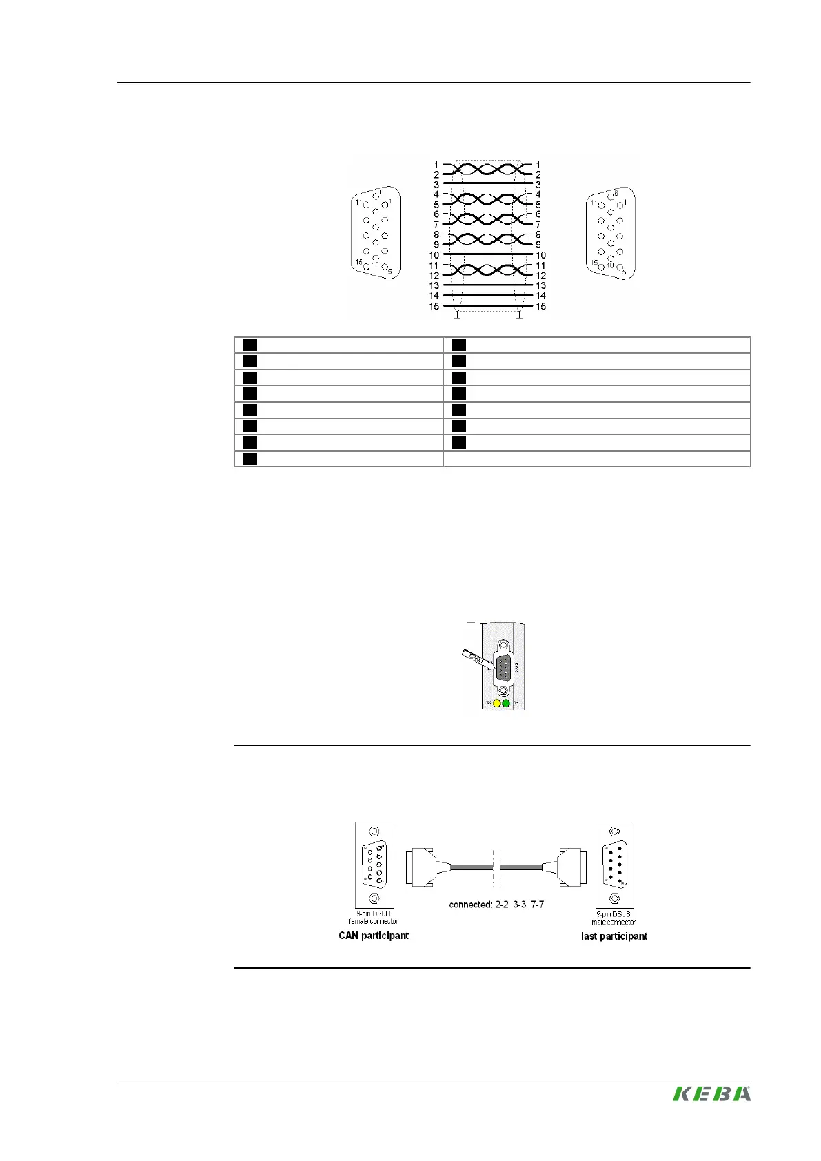
6.3.1 Pin assignment
01 ... CLK+ (Pair 1) 02 ... CLK- (Pair 1)
03 ... +5 V 04 ... RS485+ (pair 2)
05 ... RS485- (pair 2) 06 ... DATA0+ (Pair 3)
07 ... DATA0- (Pair 3) 08 ... DATA1+ (Pair 4)
09 ... DATA1- (Pair 4) 10 ... GND (connect via free line or via cable shield)
11 ... DATA2+ (Pair 5) 12 ... DATA2- (Pair 5)
13 ... SDA 14 ... SDC
15 ... Panel-present
6.3.2 Cable and plug specification
Further information: See system manual.
6.4 CAN interface (CAN0)
Fig.6-4: Position of the CAN interface (CAN0)
6.4.1 Pin assignment, connection example
Fig.6-5: CAN connection at the module: 9-pole D-SUB male connector
CP 263/S, CP 263/X
Connections and wiring
© KEBA 2014
Project engineering manual V1.01 27
 Loading...
