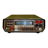
The
WARNING
heading used in this manual explain dangers
that could result in personal injury
or
death.
The
CAUTION
heading used in this manual explain hazards
that could damage the instrument.
1.6 SPECIFICATIONS
Detailed Model 197 specifications may be found preceding
the table of contents of this manual.
1.7 UNPACKING AND INSPECTION
The Model 197 Autoranging Microvolt DMM was carefully
inspected, both electrically and mechanically before ship-
ment. Upon receiving the instrument, carefully unpack all
items from the shipping carton and check for any obvious
signs of physical damage that may have occurred during tran-
sit. Report any damage to the shipping agent. Retain and use
the original packing materials in case reshipment is necessary.
The following items are shipped with every Model 197 order:
Model 197 Autoranging DMM
Model 197 Instruction Manual
Model 1751 Safety Shrouded Test Leads
Additional accessories as ordered.
If
an additional instruction manual is required, order the
manual package (Keithley Part Number 197-901-00). The
manual package includes an instruction manual and any ap-
plicable addenda.
1.8 USING THE MODEL 197 MANUAL
This manual contains information necessary for operating
and servicing the Model 197 Autoranging Microvolt DMM
and the Model 1978 Rechargeable Battery Pack. The informa-
tion is divided into the following sections.
1.
Section 2 contains detailed bench operation information
for the Model 197.
2. Section
3
contains the information needed to verify the ac-
curacy of the Model 197. Performance verification can be
done upon receipt of the unit
or
whenever the basic ac-
curacy of the instrument is in question.
3.
Information concerning theory of operation, maintenance
and servicing is contained in Sections 4 through
6.
NOTE
The Models 1973 and 1972 IEEE-488 interfaces
come supplied with their own instruction
manual.
1.9 INITIAL OPERATION
Perform the following steps in sequence to acquaint yourself
with the basic operation of the Model 197.
Verify that the instrument was not damaged in transit, (see
paragraph 1.7).
Carefully read over all safety information (see Section
2
Basic Operation).
Refer to paragraph 2.3 (Line Power) and set the line voltage
switch. Plug the power cord into a properly grounded
receptacle. If the Model 1978 is installed the charging circuit
is activated.
Acquaint yourself with the front panel controls as follows:
1.
Turn on the instrument using the ON/OFF button. All of
the zeroes are briefly displayed.
2. Connect the supplied test leads to the HI and
LO
input ter-
minals. Connect the red test lead to the HI terminal and
the black test lead to the
LO
terminal. Short the test leads
together.
3. Select AC volts and autoranging by pressing in the
AC/DC, V and AUTO buttons. The AC, AUTO and mV
annunciators are displayed. Pressing in any of the other
range buttons activates manual ranging. This is indicated
by the absence of the AUTO annunciator.
4. Select DC volts by releasing (out position) the AC/DC
button.
V
is still selected. The AC annunciator turns off.
5.
Select the autoranging OHMS by pressing in the AUTO,
and
3
buttons. DC must still be selected. The
3
(omega)
symbol is displayed. Press the AC/DC button in (means
select AC) and note that the "Err" message is displayed.
This indicates an invalid mode.
6.
Select AC or DC current by setting the AC/DC button ac-
cordingly and pressing in the A button. The annunciator
that reflects the selected mode
is
displayed. Note that cur-
rent will not autorange. The 10A and
LO
terminals must
be used on the 10A range.
7. Select dB by selecting AC
or
DC volts and pressing the dB
button. The dB annunciator is now displayed. Press the dB
button to take the instrument out of the dB mode.
8.
The REL (relative) feature can be used with any measure-
ment function: Volts, Amps, Ohms
or
dB. For example,
select the ohms function and autorange. The display reads
approximately 000.1403, which is the test lead resistance.
Press the REL button. The REL annunciator is turned on
and the display reads 000.0003. The relative level of
000.143 will be subtracted from all subsequent
measurements. Press the REL button a second time to
cancel the REL level.
1-2
Artisan Technology Group - Quality Instrumentation ... Guaranteed | (888) 88-SOURCE | www.artisantg.com

 Loading...