NOTE
It
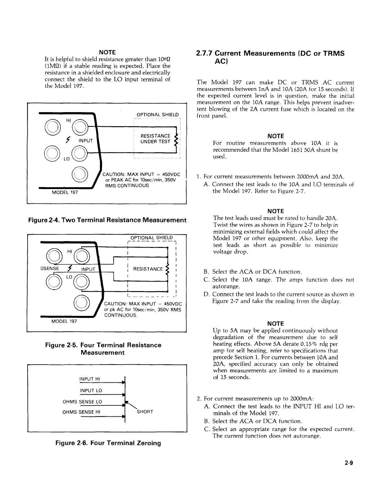
is helpful to shield resistance greater than 106Q
(1MQ)
if
a stable reading is expected. Place the
resistance in a shielded enclosure and electrically
connect the shield to the
LO
input terminal of
the Model 197.
-
OPTIONAL SHIELD
__
I
I
RESISTANCE
CAUTION: MAX INPUT
=
450VDC
or PEAK AC for lOsec/min, 350V
[
RMS CONTINUOUS
MODEL 197
Figure
2-4.
Two
Terminal Resistance Measurement
OPTIONAL SHIELD
I-----
-
-
---
I
I
CAUTION: MAX INPUT
=
450VDC
or
pk
AC for 10sec/min, 350V RMS
CONTINUOUS.
MODEL 197
Figure
2-5.
Four Terminal Resistance
Measurement
INPUT
LO
OHMS SENSE LO
OHMS SENSE HI SHORT
2.7.7
Current Measurements
(DC
or TRMS
AC)
The Model 197 can make DC or TRMS AC current
measurements between 1nA and 10A (20A for
15
seconds).
If
the expected current level is in question, make the initial
measurement on the 10A range. This helps prevent inadver-
tent blowing of the 2A current fuse which is located on the
front panel.
NOTE
For routine measurements above 10A
it
is
recommended that the Model 1651 50A shunt be
used.
1.
For current measurements between 2000mA and 20A.
A. Connect the test leads
to
the 10A and
LO
terminals
of
the Model 197. Refer
to
Figure 2-7.
NOTE
The test leads used must be rated to handle 20A.
Twist the wires as shown in Figure 2-7
to
help in
minimizing external fields which could affect the
Model 197 or other equipment. Also, keep the
test leads as short as possible
to
minimize
voltage drop.
B.
Select the ACA or DCA function.
C. Select the 10A range. The amps function does not
autorange.
D. Connect the test leads to the current source as shown in
Figure 2-7 and take the reading from the display.
NOTE
Up to
5A
may be applied continuously without
degradation of the measurement due to self
heating effects. Above
5A
derate
0.15%
rdg per
amp for self heating, refer to specifications that
precede Section
1.
For
currents between 10A and
20A, specified accuracy can only be obtained
when measurements are limited to a maximum
of
15
seconds.
2.
For
current measurements up to 2000mA:
A.
Connect the test leads to the INPUT
HI
and
LO
ter-
minals
of
the Model 197.
B.
Select the ACA or DCA function.
C.
Select an appropriate range for the expected current.
The current function does not autorange.
Figure 2-6. Four Terminal Zeroing
2-9
Artisan Technology Group - Quality Instrumentation ... Guaranteed | (888) 88-SOURCE | www.artisantg.com

 Loading...


