NOTE
Calibration may be stopped at any time and if
desired, only selected ranges may be calibrated.
FIGURE
5-2
WAS DELETED
ON
REVISION
C
OF
THIS
MANUAL.
Figure
5-2.
5.6.4 DC Voltage Calibration
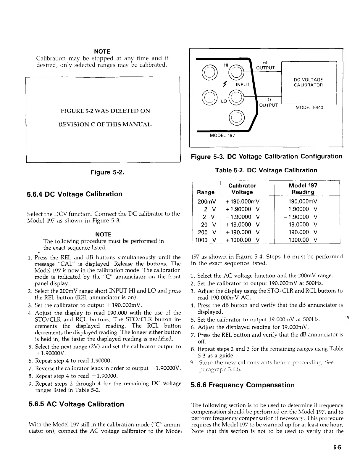
Select the DCV function. Connect the DC calibrator to the
Model
197
as shown
in
Figure
5-3.
NOTE
The following procedure must be performed in
the exact sequence listed.
1.
Press the
REL
and dB buttons simultaneously until the
message "CAL" is displayed. Release the buttons. The
Model 197
is
now in the calibration mode. The calibration
mode is indicated by the "C" annunciator on the front
panel display.
2.
Select the 200mV range short INPUT
HI
and
LO
and press
the
REL
button
(REL
annunciator is on).
3.
Set the calibrator to output +190.000mV.
4.
Adjust the display to read 190.000 with the use of the
STO/CLR and RCL buttons. The STO/CLR button in-
crements the displayed reading. The RCL button
decrements the displayed reading. The longer either button
is held in, the faster the displayed reading is modified.
5. Select the next range (2V) and set the calibrator output to
f
1.90000v.
6.
Repeat step
4
to read 1.90000.
7. Reverse the calibrator leads in order to output -1.90000V.
8.
Repeat step
4
to read -1.90000.
9. Repeat steps
2
through
4
for the remaining DC voltage
ranges listed in Table 5-2.
5.6.5 AC Voltage Calibration
With the Model 197 still in the calibration mode ("C" annun-
ciator on), connect the AC voltage calibrator to the Model
DC
VOLTAGE
CALIBRATOR
MODEL
5440
MODEL
197
Figure 5-3. DC Voltage Calibration Configuration
Table
5-2.
DC
Voltage Calibration
Range
200mV
2v
2v
20
v
200
v
1000
v
Calibrator
Voltage
+
190.000mV
+1.90000
v
-1.90000
v
+19.0000
v
+190.000
v
+1000.00
v
Model
197
Reading
190.000mV
1.90000
v
-1.90000
v
19.0000
v
190.000
v
1000.00
v
197
as shown in Figure
5-4.
Steps
1-6
must be performed
in the exact sequence listed.
1.
Select the AC voltage function and the 200mV range.
2. Set the calibrator to output 190.OOOmV at 500Hz.
3.
Adjust the display using the STO/CLR and RCL buttons to
4.
Press the dB button and verify that the dB annunciator is
read 190.OOOmV AC.
displayed.
'9
5.
Set the calibrator to output 19.OOOmV at
500Hz.
..~
6.
Adjust the displayed reading for 19.000mV.
7. Press the
REL
button and verify that the dB annunciator is
off.
8.
Repeat steps 2 and
3
for the remaining ranges using Table
5-3 as a guide.
9.
Store
the
lit317
call
constmts
hofon~
pi-occLdins.
See
p'lragraph
5.h.S.
5.6.6 Frequency Compensation
The following section is to be used to determine
if
frequency
compensation should be performed on the Model 197, and to
perform frequency compensation
if
necessary. This procedure
requires the Model 197 to be warmed up for at least one hour.
Note that this section is not to be used to verify that the
5-5
Artisan Technology Group - Quality Instrumentation ... Guaranteed | (888) 88-SOURCE | www.artisantg.com

 Loading...


