LIST
OF
ILLUSTRATIONS
2-1
2-2
2-3
2 -4
2-5
2-6
2-7
2-8
2-9
3-1
3-2
3-3
3-4
3-5
3-6
3-7
3-8
4-1
4-2
4-3
4-4
4-5
4-6
5-1
5-2
5-3
5-4
5-5
5-6
5
-7
6-1
6-2
6-3
6-4
6-5
6-6
6-7
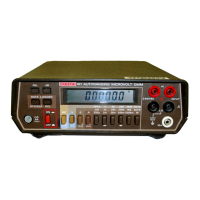
Model 197 Front Panel
.......................
.................................
2-2
DC Voltage Measurements
...................
.................................
2-6
TRMS AC Voltage Measurements
........................................................
2-7
Two Terminal Resistance Measurement
.... ....................
2-9
Four Terminal Resistance Measurement
....
....................
2-9
Four Terminal Zeroing
.........
.................................
2-9
Current Measurements Between 2
.........................................
2-10
Current Measurements up to 2000mA
.........
................................
2-10
Typical ACV Frequency Response
.......................................................
2-15
Connections for
DCV
Verification
...
..................
3-2
Connections for ACV Verification
...
..................
3-3
Connections for 200, 2k and 20k Range
...............................
3-4
Connections
for
200k through MU Ranges Verification (2-Terminal)
............................
3-4
Connections for DC Current Verification (200pA to 2000mA)
..................................
3-5
Connections for DC Current Verification (2000mA to 20A)
...................................
3-5
Connections for AC Current Verification (200pA to 2000mA)
..................................
3-6
Connections for AC Current Verification (2OOOmA to 10A)
...................................
3-6
Simplified Block Diagram
....
........................................................
4-2
4-3
Input Configuration During 2- and 4-Terminal Resistance Measurements
........................
4-4
Resistance Measurement Simplified Circuit
.................................................
4-5
A/D Converter
................................................
4-6
JFET Multiplexer
............
........................................................
4-3
Simplified Schematic of the Input Buffer Amplifier
..........................................
...........
5-3
DCI
I<TJ~:II
ON
REVISION
C
........
................................................
5-5
5-5
DC Voltage Calibration Configuration
...................................................
5-7
AC Voltage Calibration Configuration
...................................................
...........
5-7
200, 2k and 20k Four Wire Resistance Calibration
..........
...
200k. 2M and 20M
Two
Wire Resistance Calibratic
.............................
3-7
Segment Identification
...............................
...............
5-9
Model
197
Miscellaneous Parts
....
.................................................
Display Assembly, Exploded View
................................................
6-1
.........
6-7
6-11
.............................
6-15
.................
6-17
Model 1978 Battery Pack, Compone
Mother Board, Schematic Diagram, Dwg
.
No
.
197-106
......
................
.......
6-13
Model 1978 Battery Pack, Schematic Diagram, Dwg
.
No
.
1978-106
......
ion Drawing, Dwg
.
No
.
1978-100
. .
Mother Board, Component Location Drawing, Dwg
.
No
.
197-100
............
Display Board, Component Location Drawing, Dwg
.
No
.
197-110
.............................
Display Board, Schematic Diagram, Dwg
.
No
.
197-116
.....
vlvi
Artisan Technology Group - Quality Instrumentation ... Guaranteed | (888) 88-SOURCE | www.artisantg.com

 Loading...