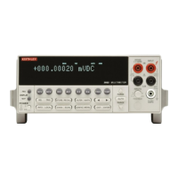
Disassembly
3-5
2.
Remove Front Panel Assembly:
The front panel as-
sembly has four retaining clips that snap onto the chassis
over four pem nut studs. Two retaining clips are located
on each side of the front panel. Pull the retaining clips
outward and, at the same time, pull the front panel as-
sembly forward until it separates from the chassis.
3.
Remove Display Board:
The display board is held in
place by a PC board stop. This stop is simply a plastic
bar that runs along the bottom edge of the display board.
Using a thin bladed screwdriver, pry the plastic bar up-
ward until it separates from the casing of the front panel.
Pull the display board out of the front panel.
4.
Remove Switch Pad:
The conductive rubber switch pad
simply pulls out of the front panel.
3.7 Cooling fan removal
The cooling fan, which is mounted to the rear panel of the
chassis, need not be removed in order to clean the filter. To
clean the filter, refer to the procedure in paragraph 1.4. If,
however, the fan must be removed, perform the following
procedure.
NOTE
In order to remove the cooling fan, the
case cover must be removed (see para-
graph 3.4.1), and the analog board must be
removed (see paragraph 3.5.3).
1.
Disconnect Fan Cable:
Turn the chassis upside-down,
and unplug the fan cable from connector J1037. This
two-conductor cable connection is located at the rear of
the digital board in front of the IEEE-488 connector. Re-
turn the chassis to the right-side-up position.
2.
Remove Mounting Nuts:
The fan is secured to the
chassis by two mounting nuts. Remove these nuts, and
pull the fan out of the chassis.
3.8 Main CPU firmware replacement
Changing the firmware may be necessary as upgrades be-
come available. The firmware revision level for the main
CPU is displayed during the power-on sequence. The firm-
ware for the main CPU is located in two EPROMS (U637
and U638) located on the digital board. (See the digital board
component layout drawing 2002-140 at the end of Section
4.)
Perform the following steps to replace the CPU firmware:
WARNING
Disconnect the instrument from the
power line and remove all test leads be-
fore changing the firmware.
1. Remove the case cover as explained in paragraph 3.4.1.
2. Turn the instrument upside down to gain access to the
digital board.
3. Locate U637 and U638 (EPROMS) on the digital board.
These two ICs are located near the center of the PC
board.
CAUTION
EPROMS U637 and U638 are static-
sensitive devices. Be sure to adhere to
the handling precautions explained in
paragraph 3.3 when replacing these de-
vices.
4. Using an appropriate chip extractor, remove U637 and
U638 from their sockets.
5. Install the new EPROMS in the appropriate sockets,
making sure that pin 1 for each device is properly orient-
ed.
NOTE
The odd-addressed EPROM must be in-
stalled at U637, and the even-addressed
EPROM must be installed at U638. The
instrument will not operate if the
EPROMS are incorrectly installed.

 Loading...