Troubleshooting
2-54
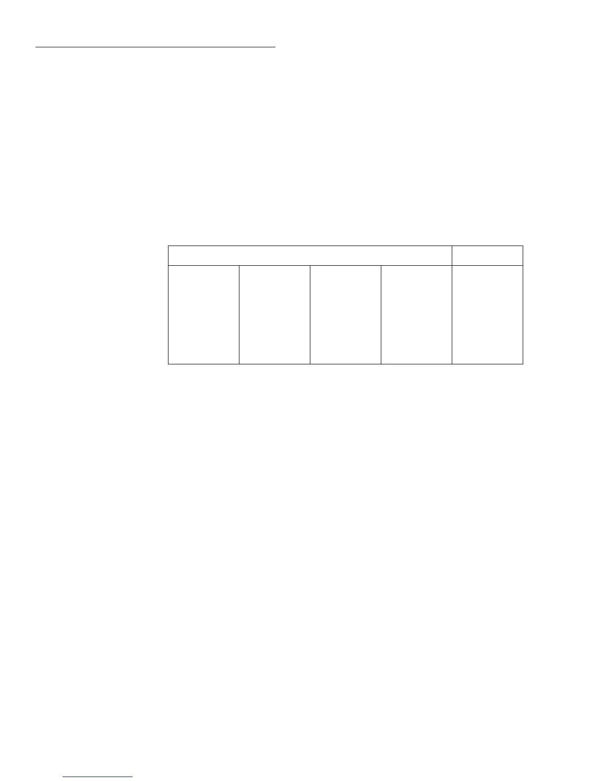
Test 302.4 — Divider LO to ADGND
Type
Pass/Fail
Fault message Divider LO to ADGND
Description Common is switched through U244 pins 11 to 10, through Q226 and Q227, through R311 and
to pin 3 of U253. U253 is the buffer for ADGND. ADGND buffer with Divider LO signal is con-
nected to the bottom of the parallel combination of R285 and R286. To ensure stability of the
circuit, X1 gain is achieved by closing U227 pins 2 to 3 with /X1 low. R274 is in the feedback
path of U226. Pin 3 of U226 is also pulled to common through U222 pin 4 and R259.
Drawing reference Analog Board; 2002-100
Components U226, U227, U244, U253, and associated components.
Bit patterns
Bit pattern* Register
—U400—
01111011
—U811—
00001101
—U224—
00010111
—U432—
10000000
—U810—
00000011
—U206—
01110000
—U203—
10001110
—U411—
11111011
—U809—
11100111
—U207—
00011110
—U221—
11101001
—U406—
00000100
AD_STB
MUX_STB
R1_STB
R2_STB
*Bits associated with register IC terminals as follows:
QQQQQQQQ
87654321 87654321 87654321 87654321
IC pins: Q8=11, Q7=12, Q6=13, Q5=14, Q4=7, Q3=6, Q2=5, Q1=4.

 Loading...


