OPERATION
INITIAL STARTING
PROCEDURE
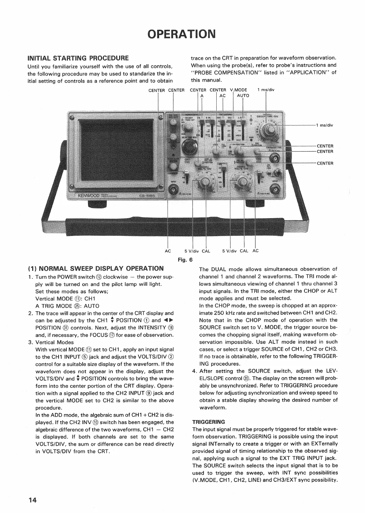
Until you familiarize yourself
with
the use of all controls,
the
following
procedure may be used to standarize the in-
itial
setting of controls as a reference
point
and to
obtain
trace on the CRT in preparation for waveform observation.
When using the probe(s), refer to probe's instructions and
"PROBE
COMPENSATION"
listed in
"APPLICATION"
of
this manual.
(1) NORMAL
SWEEP
DISPLAY OPERATION
1.
Turn the
POWER
switch © clockwise — the power sup-
ply
will
be turned on and the
pilot
lamp
will
light.
Set
these modes as follows;
Vertical MODE ©: CH1
A
TRIG
MODE @: AUTO
2.
The trace
will
appear in the center of the CRT display and
can
be adjusted by the CH1 •
POSITION
© and
POSITION
© controls. Next, adjust the
INTENSITY
©
and,
if necessary, the
FOCUS
© for
ease
of observation.
3.
Vertical Modes
With
vertical MODE © set to CH1, apply an
input
signal
to the CH1 INPUT © jack and adjust the
VOLTS/DIV
©
control
for a suitable
size
display of the waveform. If the
waveform does not appear in the display, adjust the
VOLTS/DIV
and •
POSITION
controls to
bring
the wave-
form
into
the center
portion
of the CRT display. Opera-
tion
with
a signal applied to the CH2 INPUT © jack and
the vertical MODE set to CH2 is similar to the above
procedure.
In the ADD mode, the algebraic sum of CH1 + CH2 is dis-
played.
If the CH2 INV © switch has been engaged, the
algebraic difference of the two waveforms, CH1 — CH2
is
displayed. If
both
channels are set to the same
VOLTS/DIV,
the sum or difference can be read directly
in
VOLTS/DIV
from
the CRT.
The
DUAL mode allows simultaneous observation of
channel 1 and channel 2 waveforms. The TRI mode al-
lows simultaneous viewing of channel 1
thru
channel 3
input
signals. In the TRI mode, either the
CHOP
or ALT
mode applies and must be selected.
In the
CHOP
mode, the sweep is chopped at an approx-
imate 250 kHz rate and switched between CH1 and CH2.
Note
that
in the
CHOP
mode of operation
with
the
SOURCE
switch set to V. MODE, the
trigger
source be-
comes
the chopping signal itself, making waveform ob-
servation impossible. Use ALT mode instead in such
cases,
or select a
trigger
SOURCE
of CH1, CH2 or CH3.
If no trace is obtainable, refer to the
following
TRIGGER-
ING
procedures.
4.
After setting the
SOURCE
switch, adjust the
LEV-
EL/SLOPE
control
(20).
The display on the screen
will
prob-
ably be unsynchronized. Refer to
TRIGGERING
procedure
below for adjusting synchronization and sweep speed to
obtain
a stable display showing the desired number of
waveform.
TRIGGERING
The
input
signal must be properly
triggered
for stable wave-
form
observation.
TRIGGERING
is possible using the
input
signal INTernally to create a
trigger
or
with
an EXTernally
provided signal of
timing
relationship to the observed
sig-
nal,
applying such a signal to the EXT
TRIG
INPUT jack.
The
SOURCE
switch selects the
input
signal
that
is to be
used
to
trigger
the sweep,
with
INT sync possibilities
(V.MODE,
CH1, CH2,
LINE)
and
CH3/EXT
sync possibility.
14
Fig.
6
 Loading...


