PHASE
DIFFERENCE
MEASUREMENTS
This
procedure is useful in measuring the phase difference
of signals of the same frequency.
Procedure:
1.
Apply the two signals to the CH1 and CH2
INPUT
jacks,
setting the vertical MODE to either
CHOP
or ALT mode.
2.
Set the
SOURCE
to the signal which is leading in phase
and use the
VOLTS/DIV
to adjust the signals such that
they are equal in amplitude. Adjust the other controls for
a
normal display.
3.
Use the
SWEEP
TIME/DIV
and
SWEEP
VARIABLE
to ad-
just the display such that one cycle of the signals oc-
cupies
8 divisions of horizontal display.
Use
the *
POSITION
to bring the signals in the center
of the
screen.
Having set up the display as above, one division now
represents
45° in phase.
4.
Measure the horizontal distance between corresponding
points on the two waveforms.
Using
the formula:
Phase
difference = Horizontal distance (div) x 45°/div
[EXAMPLE]
For
the example, the horizontal distance is 1.7 divisions.
(See
Fig. 26)
Substituting the given value:
The
phase difference = 1.7 (div)x45°/div= 76.5°
The
above setup allows 45° per division but if more ac-
curacy
is required the
SWEEP
TIME/DIV
may be changed
and magnified
without
touching the
VARIABLE
control and
if necessary the trigger level can be readjusted.
In this
case,
the phase difference can be obtained
from
the
SWEEP
TIME/DIV
setting for 8 divisions/cycle and the new
SWEEP
TIME/DIV
setting changed for higher accuracy, by
useing
the
following
formula.
Phase
difference = Horizontal distance of new sweep range
(div)x45°/div
New
SWEEP
TIME/DIV
setting
X
Original
SWEEP
TIME/DIV
setting
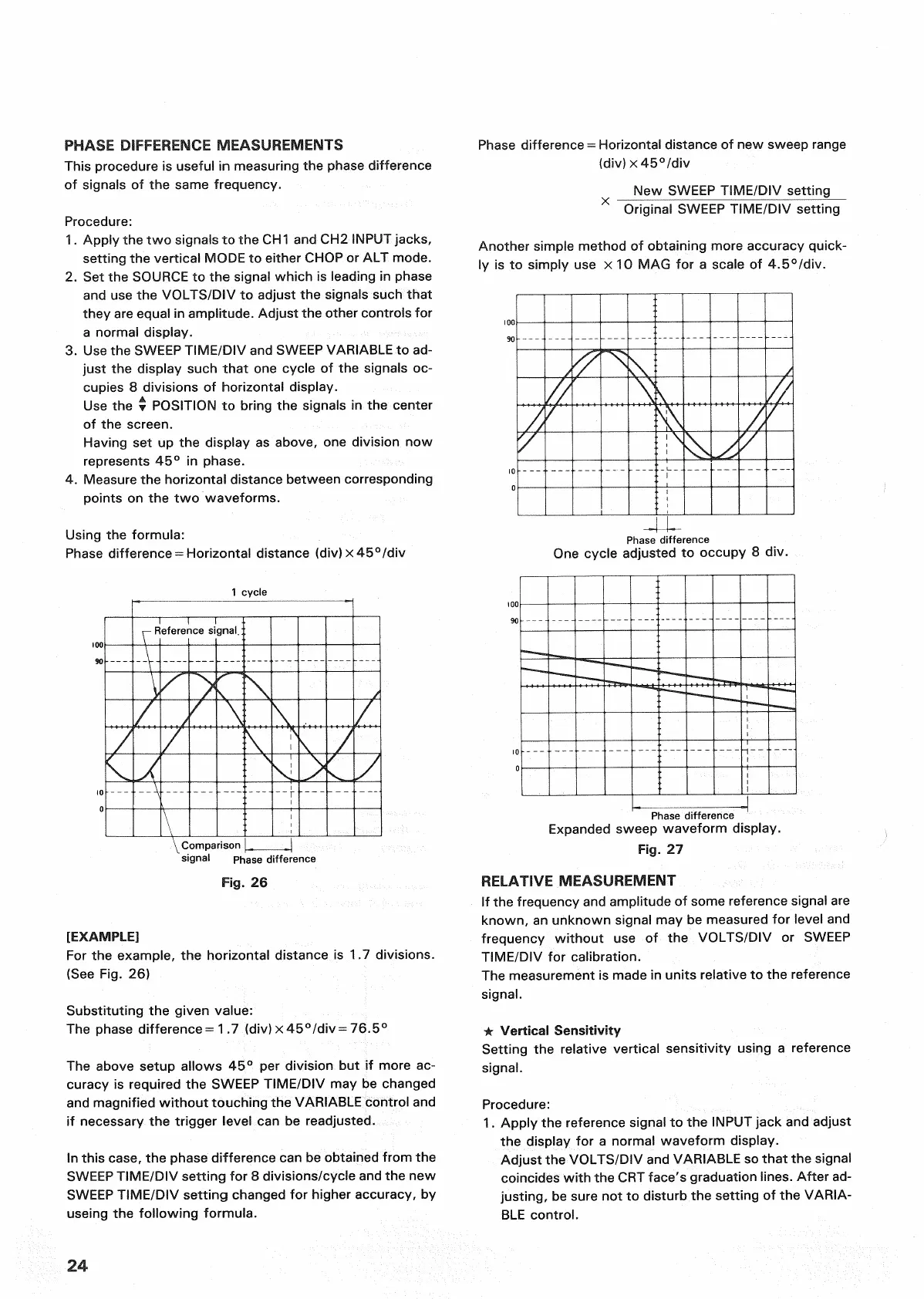
Another simple method of obtaining more accuracy quick-
ly is to simply use x 10 MAG for a
scale
of 4.5°/div.
One
cycle adjusted to occupy 8 div.
RELATIVE
MEASUREMENT
If the frequency and amplitude of some reference signal are
known, an unknown signal may be measured for level and
frequency
without
use of the
VOLTS/DIV
or
SWEEP
TIME/DIV
for calibration.
The
measurement is made in units relative to the reference
signal.
• Vertical Sensitivity
Setting the relative vertical sensitivity using a reference
signal.
Procedure:
1.
Apply the reference signal to the
INPUT
jack and adjust
the display for a normal waveform display.
Adjust the
VOLTS/DIV
and
VARIABLE
so that the signal
coincides
with
the CRT
face's
graduation lines. After ad-
justing, be sure not to disturb the setting of the
VARIA-
BLE
control.
24
Phase
difference
1
cycle
Reference
signal.
Comparison
signal
Phase
difference
Fig.
26
Phase
difference
Expanded
sweep waveform display.
Fig.
27
 Loading...


