(2) MAGNIFIED
SWEEP
OPERATION
Since
merely shortening the sweep time to magnify a
por-
tion
of an observed waveform can result in the desired
por-
tion
disappearing off the
screen,
such magnified display
should be performed using the MAGNIFIED
SWEEP.
Using
the O
POSITION
control, adjust the desired
por-
tion
of waveform to the CRT. Pull the
PULLx
10 MAG ©
control to magnify the display 10 times. For this type of dis-
play the sweep time is the
SWEEP
TIME/DIV
setting divid-
ed by 10.
(3) ALTERNATING
SWEEP
OPERATION
A
sweep and B delayed sweep are usable in an alternating
fashion making it possible to observe
both
the normal and
magnified waveform simultaneously.
Procedure:
1.
Set the
HORIZ
MODE to A and adjust for a normal wave-
form
display.
2.
Set the B
TRIG
MODE to
AFTER
DELAY
and set the HO-
RIZ
MODE to ALT. Adjust
TRACE
SEPATATION
(§) for
easy
observation of
both
the A and B traces. The upper
trace
is the non-magnified
portion
of the waveform
with
the magnified
portion
super-imposed as an intensified
section.
The lower waveform is the intensified
portion
displayed magnified.
3.
The
DELAY
TIME
MULT can be used to continuously slide
the magnified
portion
of the waveform
across
the A
sweep
period to allow magnification of precisely the
desired
portion
of waveform. To magnify the
front
part
of the sweep, set B
TRIG
MODE © to
DELAY
= 0.
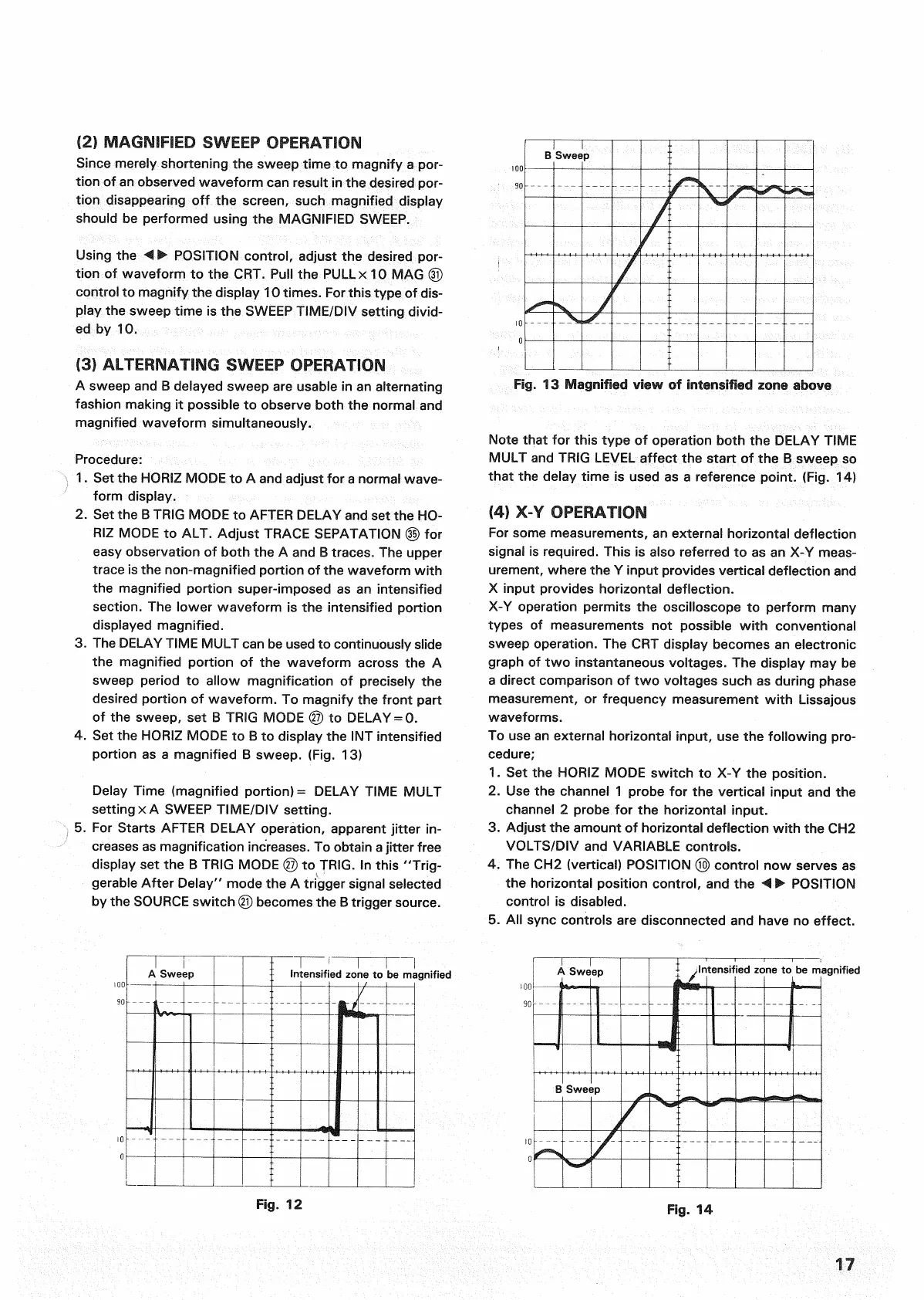
4.
Set the
HORIZ
MODE to B to display the INT intensified
portion
as a magnified B sweep. (Fig. 13)
Delay
Time (magnified portion) =
DELAY
TIME
MULT
settingx A
SWEEP
TIME/DIV
setting.
5.
For Starts
AFTER
DELAY
operation, apparent
jitter
in-
creases
as magnification
increases.
To obtain a
jitter
free
display set the B
TRIG
MODE © to
TRIG.
In this "Trig-
gerable After Delay" mode the A trigger signal selected
by the
SOURCE
switch © becomes the B trigger source.
Fig.
13 Magnified view of intensified zone above
Note that for this type of operation
both
the
DELAY
TIME
MULT
and
TRIG
LEVEL
affect the start of the B sweep so
that the delay time is used as a reference
point.
(Fig. 14)
(4) X-Y OPERATION
For
some measurements, an external horizontal deflection
signal
is required.
This
is also referred to as an X-Y
meas-
urement, where the Y
input
provides vertical deflection and
X
input
provides horizontal deflection.
X-Y
operation permits the oscilloscope to perform many
types
of measurements not possible
with
conventional
sweep
operation. The CRT display becomes an electronic
graph of two instantaneous voltages. The display may be
a
direct comparison of two voltages such as during phase
measurement,
or frequency measurement
with
Lissajous
waveforms.
To
use an external horizontal
input,
use the
following
pro-
cedure;
1.
Set the
HORIZ
MODE switch to X-Y the position.
2.
Use the channel 1 probe for the vertical
input
and the
channel
2 probe for the horizontal
input.
3.
Adjust the amount of horizontal deflection
with
the CH2
VOLTS/DIV
and
VARIABLE
controls.
4.
The CH2 (vertical)
POSITION
© control now
serves
as
the horizontal position control, and the < •
POSITION
control is disabled.
5.
All
sync
controls are disconnected and have no effect.
A
Sweep
Intensified zone to be magnified
Fig.
12
Fig.
14
17
B
Sweep
A
Sweep
B
Sweep
.Intensified zone to be magnified
 Loading...


