TK-760/762
CIRCUIT
DESCRIPTION
3.
Transmitter
System
3-1. Microphone amplifier
The signal from the microphone goes to the micro-
phone
mute
switch
(0403
off). It then passes through
the high-pass filter
in
IC402 (2/2) and the pre-empha-
sis/IDC circuit
in
IC402 (1/2).
The signal
is
applied to the IC404 summing amplifier
and
mixed with
OT
and DOT from the
CPU
(IC409). It
then passes through the splatter filter (the fourth low-
pass filter) consisting
of
IC406 (1/2, 2/2),
which
re-
moves unwanted harmonics.
The output from the low-pass filter
is
input to the D/
A
converter
(IC6)
to
adjust
the
modulation.
IC6
changes the deviations of the wide
and
narrow chan-
nels.
From
Microphone
Q403 IC402 (2/2)
IC404
D/A Converter
IC6
Fig. 4 Microphone amplification
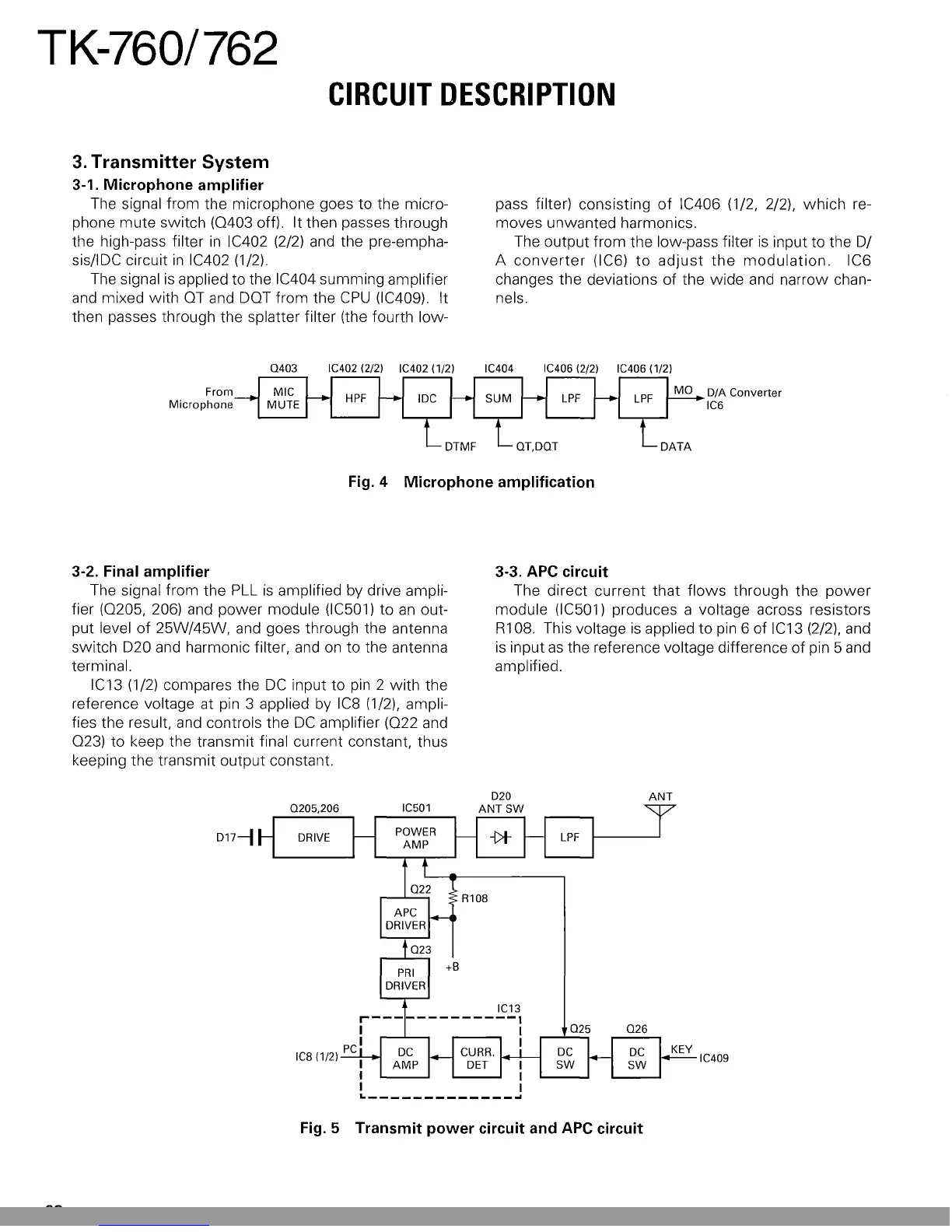
3-2. Final amplifier
The signal from the
PLL
is
amplified by drive ampli-
fier (0205, 206) and power module (IC501) to
an
out-
put level
of
25W/45W, and goes through the antenna
switch D20 and harmonic filter, and
on
to the antenna
terminal.
IC13 (1/2) compares the
DC
input to
pin
2
with
the
reference voltage at pin 3 applied
by
IC8
(1/2), ampli-
fies the result, and controls the
DC
amplifier
(022
and
023) to keep the transmit final current constant, thus
keeping the transmit output constant.
3-3. APC circuit
The direct current that
flows
through the
power
module (IC501) produces a voltage across resistors
R108. This voltage
is
applied
to
pin 6 of IC13 (2/2), and
is
input
as
the reference voltage difference of pin 5 and
amplified.
D17-1
IC409
Fig. 5 Transmit
power
circuit and
APC
circuit
22
This Manual: http://www.manuallib.com/file/2593611
 Loading...