TK-760/762
CIRCUIT
DESCRIPTION
GRN RED
r-----'I
D412
I
// //
I :
IMONI
L _
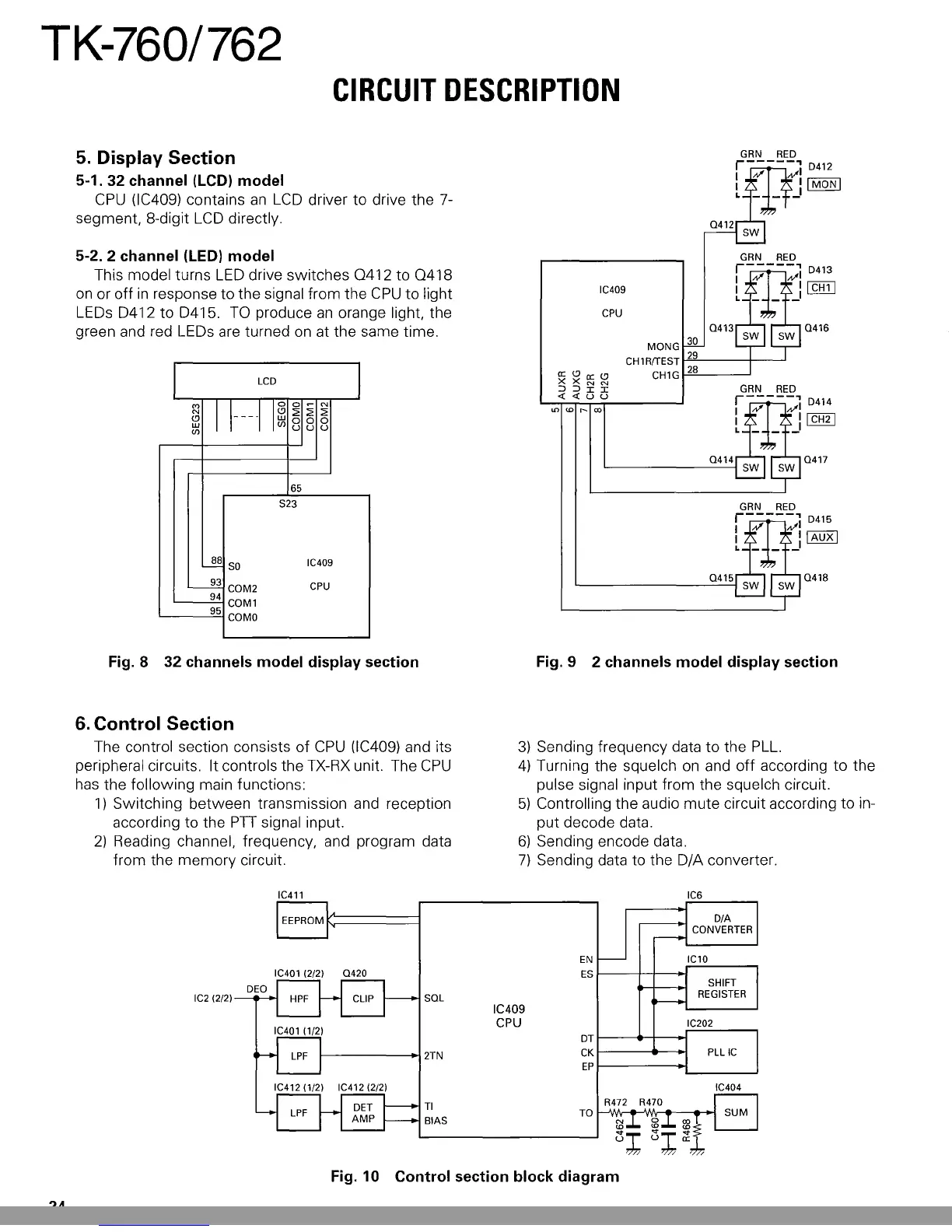
5.
Display Section
5-1. 32 channel
(LCD)
model
CPU
(lC409) contains
an
LCD
driver to drive the 7-
segment, 8-digit
LCD
directly.
5-2. 2 channel (LED) model
This model turns
LED
drive switches
0412
to
0418
on
or off
in
response to the signal from the
CPU
to light
LEDs D412 to D415.
TO
produce
an
orange light, the
green and red LEDs are turned
on
at the same time.
LCD
I
M
1
1---·1
1
~
o~
N
N
:2::2:
:2:
<.9
00
0
w
uu
u
(J)
65
S23
~
SO
IC409
~
COM2
CPU
94
COM1
95
COMO
IC409
CPU
0413
MONG
30
CH
1
RrrEST
1-"2",-9
----t-----'
CH1
G
1-'2"'-8
__
--'
0414
0415
0416
0417
0418
Fig. 8 32 channels model display section Fig. 9 2 channels model display section
6.
Control Section
The control section consists of
CPU
(lC409) and its
peripheral circuits. It controls the
TX-RX
unit. The
CPU
has the following main functions:
1)
Switching between transmission and reception
according to the
PTI
signal input.
2)
Reading channel, frequency, and program data
from the memory circuit.
3)
Sending frequency data
to
the
PLL.
4)
Turning the squelch
on
and
off
according
to
the
pulse signal input from the squelch circuit.
5)
Controlling the audio mute circuit according to in-
put decode data.
6)
Sending encode data.
7)
Sending data to the D/A converter.
EN
IC401 (2/2)
0420
ES
IC2 (2/2)
SOL
IC409
CPU
DT
2TN
CK
EP
IC404
TI
TO
BIAS
Fig. 10 Control section block diagram
24
This Manual: http://www.manuallib.com/file/2593611
 Loading...