TK-8102
12
INSTALLATION
1. Optional Board
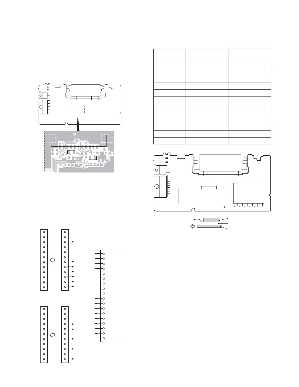
1-1. Voice Scrambler Board Connection
■ Modification
1. Remove the cabinet and shielding cover from the trans-
ceiver.
2. Delete R202 and R267 on the TX-RX unit.
A
9
8
7
D
C
B
A
A12
1
3
7
8
9
10
11
12
1
12
BA11
CA10
DA9
E
1
2
3
4
5B5
6B7
7A8
8A7
9A3
10B11
11B9
12B4
E18
Voice scrambler
board
12 pins lead wire
with connector (A)
E37-1081-05
CN2
12
6
5
11
10
1
4
5
7
9
11
1
11
11 pins lead wire
with connector (B)
E37-1080-05
CN3
■ Connection
The functions of pins of CN2 and CN3 on the TX-RX unit
are shown in the TERMINAL FUNCTION section (page 37).
Fig. 1
Fig. 2
R267
CN3
R202
TX-RX UNIT
Component side
■ Pins Connection
Voice scrambler
12 pins lead wire 11 pins lead wire
functions with connector (A) with connector (B)
A A-12 –
B A-11 –
C A-10 –
D A-9 –
5– B-5
6– B-7
7 A-8 –
8 A-7 –
9 A-3 –
10 – B-11
11 – B-9
12 – B-4
■ Setting With the KPG-70D
Select “External Devices” from the “Edit” menu and set
the “Scrambler”.
Note :
The voice scrambler board is connected subsequent to the
de-emphasis circuit.
Cushion (G13-1963-04)
Cushion (G13-1964-04)
Voice scrambler board
Front side
to CN2 and CN3
to CN2
and CN3
CN3
Voice scrambler
board
CN2
TX-RX UNIT
Component side
Fig. 3
 Loading...