TK-8102
9
4. Clone Mode
Programming data can be transferred from one radio to
another by connecting them via their modular microphone
jacks. The operation is as follows (the transmit radio is the
master and the receive radio is the slave).
Note :
Clone mode should enabled.
1. Turn the master TK-8102 power ON with the [1] key held
down. The TK-8102 [●] LED is turned on.
2. Power on the slave TK-8102H.
3. Connect the cloning cable (No. E30-3382-05) to the modu-
lar microphone jacks on the master and slave.
4. Press the [●] key on the master TK-8102 transceiver. The
data of the master is sent to the slave. While the master is
sending data, [TX] LED blinked. While the slave is receiv-
ing the data, 4 LEDs, [MON] LED, [●] LED are turned on
and [BUSY] LED blinked. When cloning of data is com-
pleted, the master [TX] LED turned off, and the slave auto-
matically operates in the User mode. The slave can then
be operated by the same program as the master.
5. The other slave can be continuously cloned. Carry out the
operation in step 2 to 4.
4-1. Adding the data password.
If the data password is set in the optional feature menu,
you must enter the password (Master transceiver) to activate
a clone mode.
you can use 1, 2, 3, and 4 to configure the password. The
maximum length of the password is 10 digits.
1. [1]+Power ON.
2. [1]~[4] LED, and MON LED are turned ON.
3. Enter the password using [1]~[4] keys.
4. Press [MON] key.
5. If the password matches, the transceiver enters a clone
mode. Otherwise, transceiver beeps and returns to the
password input mode.
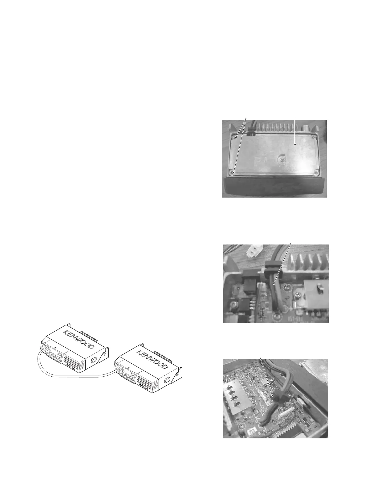
Fig. 2
Clone cable
(E30-3382-05)
REALIGNMENT
5. Accessory Connection Cable (KCT-39)
The KCT-39 is an accessory connection cable for connect-
ing external equipment. The connector has 15 pins and the
necessary signal lines are selected for use.
1. Unscrew the five M2.6 screws (N87-2614 -46), then re-
move the shielding cover (F10-2491-03).
2. Lift the DC cord (E30 -3448 -05) and remove the cushion
(G13 -2003 -04) from the chassis.
M2.6 screws
Shielding cover
DC cord
Cushion
3. Attach a new cushion (G13-1960 -08) to the DC bush.
 Loading...