EasyManuals Logo
Home>Key Automation>Control Unit>CT202 24

Key Automation CT202 24 User Manual

Key Automation CT202 24
Go to English
116 pages
To Next Page IconTo Next Page
To Previous Page IconTo Previous Page
Page #6 background imageLoading...
Page #6 background image
6
IT
4 - INSTALLAZIONE DEL PRODOTTO
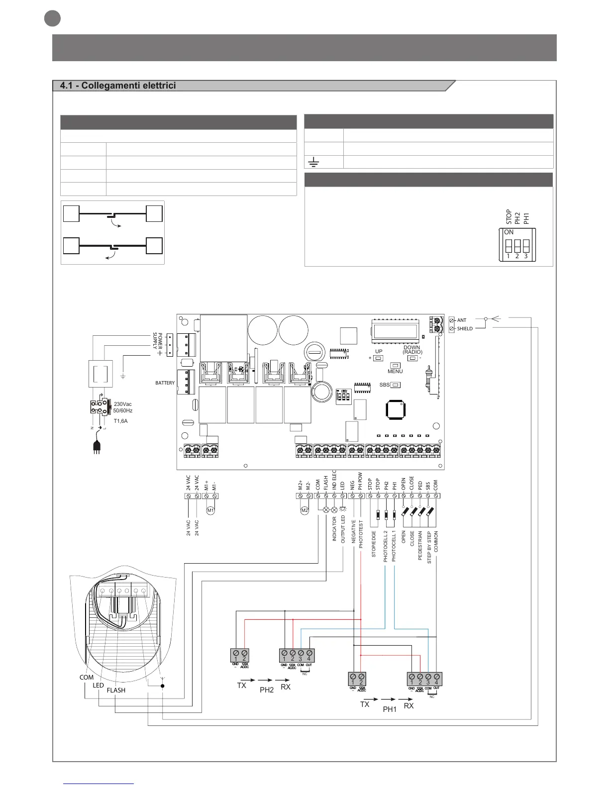
4.1 - Collegamenti elettrici
ATTENZIONE - Prima di effettuare i collegamenti vericare che la centrale non sia alimentata
PHOTOTEST
OUTPUT LED
OPEN
PHOTOCELL 1
PHOTOCELL 2
CLOSE
PEDESTRIAN
STEP BY STEP
COMMON
STOP/EDGE
INDICATOR
NEGATIVE
24 VAC
24 VAC
M1 M2
2
3
4
1
1
2
TX
RX
NC
PH2
2
3
4
1
1
2
TX
RX
PH1
GND
_
12/24
AC/DC
GND
_
12/24
AC/DC
COM
OUT
GND
_
12/24
AC/DC
GND
_
12/24
AC/DC
COM
OUT
NC
N
T1,6A
L
230Vac
50/60Hz
COM
LED
FLASH
24 VAC
24 VAC
M1+
M1-
M2+
M2-
COM
FLASH
IND ELEC
LED
NEG
PH POW
STOP
STOP
PH2
PH1
OPEN
CLOSE
SBS
PED
COM
BATTERY
SHIELD
ANT
POWER
SUPPLY
UP
+
-
MENU
SBS
DOWN
(RADIO)
ON
1 2 3
STOP
PH2
PH1
COLLEGAMENTO MOTORI
Morsettiera collegamenti alimentazione
M1 + Alimentazione motore M1 +
M1 - Alimentazione motore M1 -
M2 + Alimentazione motore M2 +
M2 - Alimentazione motore M2 -
CONNETTORE ALIMENTAZIONI
L Fase alimentazione 230 Vac (120 Vac) 50-60 Hz
N Neutro alimentazione 230 Vac (120 Vac) 50-60 Hz
Terra
SELETTORE DIP SWITCH
Settato su “ON” disabilita gli ingressi STOP, PH1, PH2
Elimina la necessita’ di ponticellare gli ingressi su morsettiera.
ATTENZIONE - con dip switch in ON
le sicurezze collegate sono escluse
M1M2
M2M1

Table of Contents

Questions and Answers:

Question and Answer IconNeed help?

Do you have a question about the Key Automation CT202 24 and is the answer not in the manual?

Key Automation CT202 24 Specifications

General IconGeneral
BrandKey Automation
ModelCT202 24
CategoryControl Unit
LanguageEnglish

Related product manuals