EasyManuals Logo
Home>Key Automation>Control Unit>CT202 24

Key Automation CT202 24 User Manual

Key Automation CT202 24
Go to English
116 pages
To Next Page IconTo Next Page
To Previous Page IconTo Previous Page
Page #70 background imageLoading...
Page #70 background image
70
DE
4 - PRODUKTINSTALLATION
4.1 - Stromanschlüsse
ACHTUNG - Vor dem Anschluss sicherstellen, dass die Stromzufuhr des Steuergerätes abgeschaltet ist.
ON
1 2 3
STOP
PH2
PH1
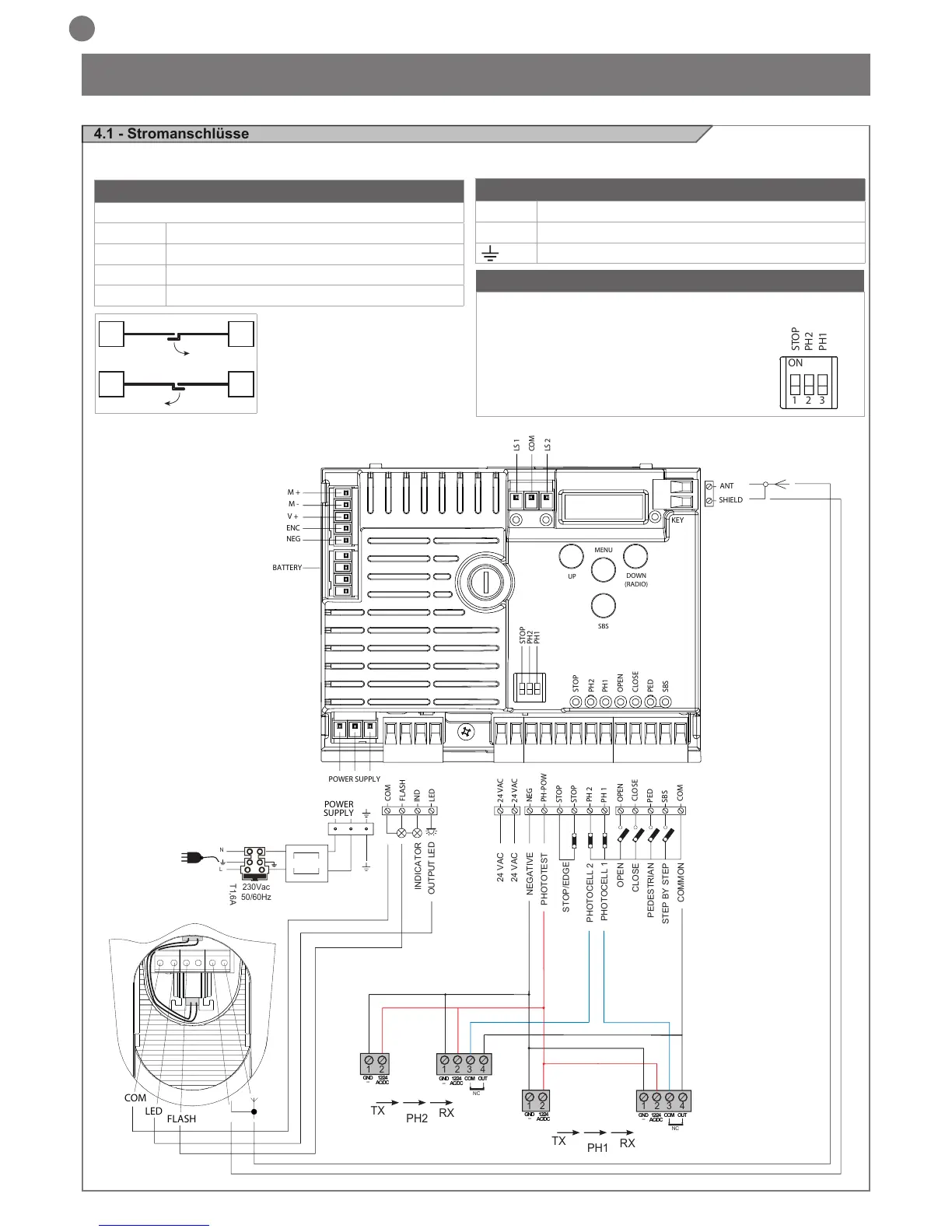
ANSCHLUSS DER MOTOREN
Klemmenleiste Versorgungsanschlüsse
M1 + Stromversorgung Motor M1 +
M1 - Stromversorgung Motor M1 -
M2 + Stromversorgung Motor M2 +
M2 - Stromversorgung Motor M2 -
STROMVERBINDER
L Phase 230 Vac (120 Vac) 50-60 Hz
N Nullleiter 230 Vac (120 Vac) 50-60 Hz
Erde
WÄHLSCHALTER DIP SWITCH
Bei Einstellung auf „ON“ sperrt er die Eingänge STOP, PH1, PH2.
Dadurch entfällt die Notwendigkeit, die Eingänge auf der
Klemmenleiste zu überbrücken.
ACHTUNG - Bei Einstellung des Dip
Switch auf ON sind die angeschlossenen
Sicherheitsvorrichtungen ausgeschlossen.
NEG
PH-POW
STOP
STOP
PH 2
COM
FLASH
IND
LED
24 VAC
24 VAC
PH 1
OPEN
CLOSE
SBS
PED
COM
PHOTOTEST
OUTPUT LED
OPEN
PHOTOCELL 1
PHOTOCELL 2
CLOSE
PEDESTRIAN
STEP BY STEP
COMMON
STOP/EDGE
INDICATOR
NEGATIVE
24 VAC
24 VAC
2
3
4
1
1
2
TX
RX
NC
PH2
2
3
4
1
1
2
TX
RX
PH1
GND
_
12/24
AC/DC
GND
_
12/24
AC/DC
COM
OUT
GND
_
12/24
AC/DC
GND
_
12/24
AC/DC
COM
OUT
NC
POWER
POWER SUPPLY
SUPPLY
N
T1,6A
L
230Vac
50/60Hz
COM
LED
FLASH
STOP
STOP
PH2
PH1
OPEN
CLOSE
PED
SBS
PH2
PH1
SHIELD
UP
MENU
SBS
DOWN
(RADIO)
ANT
NEG
ENC
V +
M -
M +
BATTERY
LS 1
LS 2
KEY
COM
M1M2
M2M1

Table of Contents

Questions and Answers:

Question and Answer IconNeed help?

Do you have a question about the Key Automation CT202 24 and is the answer not in the manual?

Key Automation CT202 24 Specifications

General IconGeneral
BrandKey Automation
ModelCT202 24
CategoryControl Unit
LanguageEnglish

Related product manuals