69
DE
3 - VORABKONTROLLEN
2.4 - Liste benötigter Kabel
Die bei einer typischen Anlage erforderlichen Kabel für den An-
schluss der einzelnen Vorrichtungen sind in der Tabelle Kabelliste
aufgeführt.
Vor der Installation bitte folgende Punkte prüfen und kontrollieren:
Prüfen, dass das Tor, die Tür oder die Schranke für eine Automati-
sierung geeignet sind;
das Gewicht und die Abmessungen des Tores bzw. der Tür sowie
der Ausgleich des Schrankenbaums müssen innerhalb der Einsatz-
Grenzbestimmungen des Antriebes liegen, auf den das Produkt in-
stalliert wird;
kontrolle des Vorhandenseins und der Stärke der mechanischen
Sicherheitsanschläge des Tors oder der Tür;
sicherstellen, dass der Befestigungsbereich nicht überutet werden
kann;
überhöhter Säure- oder Salzgehalt oder die Nähe von Wärmequel-
len können eine Funktionsstörung des Produktes verursachen;
bei extremen klimatischen Verhältnissen (wie z. B. Schnee, Eis,
hohe Temperaturunterschiede, hohe Temperaturen) könnten sich
die Reibungen verstärken; deshalb könnte der Kraftaufwand für
die Bewegung und das Anlaufmoment höher sein als im Normalzu-
stand;
kontrollieren, dass eine sanfte manuelle Bewegung des Tors, der
Tür bzw. Schranke ohne Stellen mit stärkerem Widerstand möglich
ist und dass kein Risiko des Austreten aus den Führungsschienen
besteht;
kontrollieren, dass das Tor, die Tür bzw. Schranke im Gleichgewicht
sind und daher in jeder beliebigen Position stehen bleiben;
prüfen, dass die Stromleitung für den Anschluss des Produkts über
eine Sicherheitserdung verfügt und mit einem Leitungsschutz- und
Differentialschalter geschützt ist;
im Stromnetz der Anlage eine Abschaltvorrichtung mit ausreichen-
dem Öffnungsabstand der Kontakte vorsehen, die, wie von der
Überspannungskategorie III gefordert, die komplette Abschaltung
erlaubt;
sicherstellen, dass das gesamte für die Installation benutzte Mate-
rial den geltenden Bestimmungen entspricht.
Die benutzten Kabel müssen dem Installationstyp entsprechen; z. B.
wird ein Kabel des Typs H03VV-F für Innenbereiche bzw. H07RN-F
für Außenbereiche empfohlen.
* Wenn das Versorgungskabel länger als 30 ist, muss ein Kabel mit größerem Querschnitt benutzt (3x2,5 mm
2
) und eine Sicherheitserdung
in der Nähe der Automatisierung installiert werden.
** Alternativ können zwei Kabel 2 x 0,5 mm
2
verwendet werden
TECHNISCHE SPEZIFIKATIONEN FÜR ELEKTRISCHE KABEL
Anschluss kabelliste maximal zulässige Grenze
Elektrische Versorgungsleitung 1 x kabel 3 x 1,5 mm
2
20 m *
Blinkleuchte, zusätzliche Beleuchtung
Antenne
3 x 0,5 mm
2
**
1 x kabel typ RG58
20 m
20 m (empfohlen < 5 m)
Elektroschloss 1 x kabel 2 x 1 mm
2
10 m
Fotozellen Sender 1 x kabel 2 x 0,5 mm
2
20 m
Fotozellen Empfänger 1 x kabel 4 x 0,5 mm
2
20 m
Schaltleiste 1 x kabel 2 x 0,5 mm
2
20 m
Schlüsseltaster 1 x kabel 4 x 0,5 mm
2
** 20 m
Motorstromleitung 1 x kabel 2 x 1,5 mm
2
10 m
- Gegen Kurzschlüsse im Steuergerät, an den Motoren und am an-
geschlossenen Zubehör geschützte Versorgung.
- Hinderniserkennung.
- Automatisches Erlernen der Arbeitszeit.
- Ausschaltung der Sicherheitseingänge durch Dip Switch: Die
Klemmen der nicht installierten Sicherheitsvorrichtungen müssen
nicht überbrückt werden; es reicht aus, die Funktion mit Dip Switch
zu sperren.
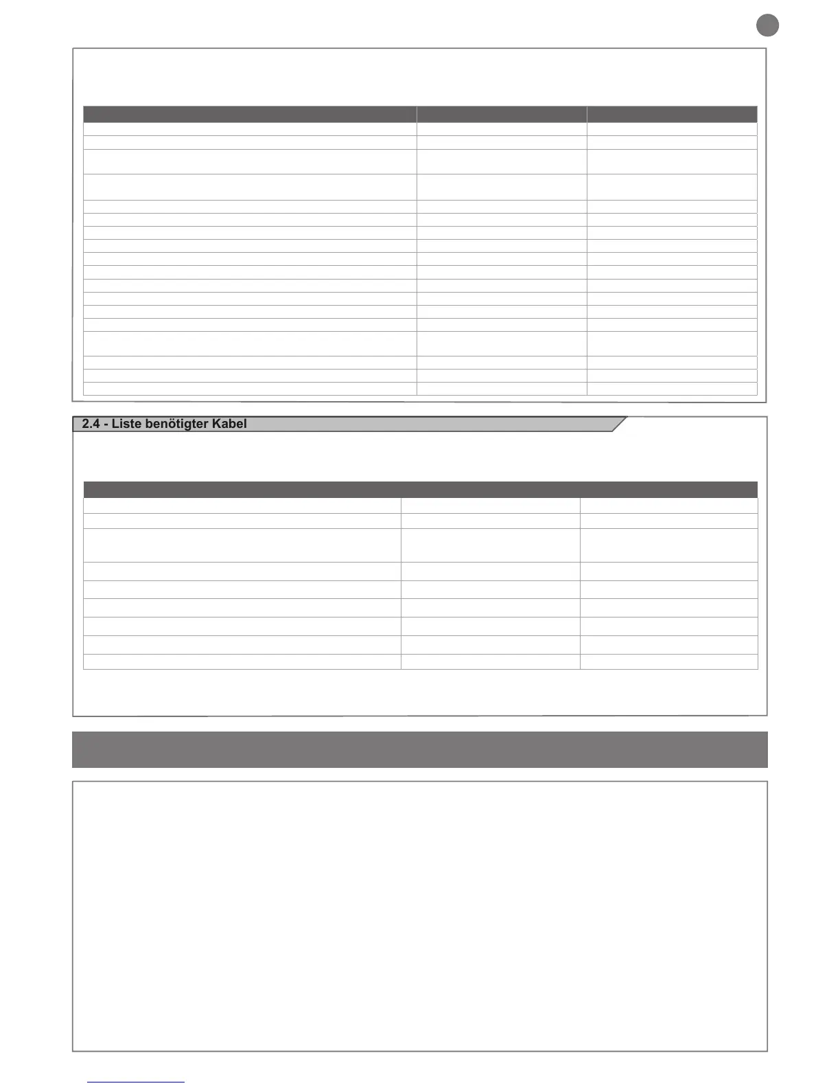
TECHNISCHE MERKMALE CT202 24 CT202 24L
Spannungsversorgung (L-N) 230Vac (+10% - 15%) 50/60 Hz 115Vac (+10% - 15%) 50/60 Hz
Nennleistung 210W maximal 210W maximal
Ausgang Spannungsversorgung Fotozellen
24Vdc (ungeregelt) maximal
250mA
24Vdc (ungeregelt) maximal
250mA
Ausgang Spannungsversorgung Zubehör Vac / Spannungsversorgung
Gerätetest Vdc
24 Vac ungeregelt 200 mA /
24 Vdc ungeregelt 250 mA
24 Vac ungeregelt 200 mA /
24 Vdc ungeregelt 250 mA
Ausgang Blinkleuchte 24Vdc (ungeregelt) 15W 24Vdc (ungeregelt) 15W
Ausgang zusätzliche Beleuchtung 24Vdc (ungeregelt) 15W 24Vdc (ungeregelt) 15W
Ausgang Elektroschloss 12Vac 15VA maximal 12Vac 15VA maximal
Ausgang Kontrollleuchte Tor geöffnet 24Vdc (ungeregelt) 5W 24Vdc (ungeregelt) 5W
Eingang Antenne 50Ω Kabel Typ RG58 50Ω Kabel Typ RG58
Betriebstemperatur -20°C + 55°C -20°C + 55°C
Sicherungen Zubehör 2AT 2AT
Sicherungen Versorgungsleitung 1.6AT 3.15AT
Max. Anzahl speicherbare FIX CODE Sender 150 150
Max. Anzahl speicherbare ROLLING CODE Sender 150 150
Benutzung in besonders säure- oder salzhaltiger oder explosiver
Umgebung
NEIN NEIN
Schutzart IP54 IP54
Abmessungen des Steuergerätes 222 x 110 x 275 H mm 222 x 110 x 275 H mm
Gewicht 3,93 kg 3,93 kg