14
EN
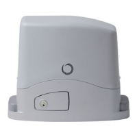
4 - PRODUCT INSTALLATION
ATTENTION !
The installer must verify that the working temperature range
stated on the automation device is suitable for the location
where it is installed.
ATTENTION !
The automation system must be equipped with a pressure-
sensitive edge protecting all possible crushing points (han-
ds, feet, etc.) in accordance with the requirements of the EN
13241-1 standard.
ATTENTION !
ATTENZIONE !
The gate has to be equipped with stop locks at the opening
and closing, which prevent the gate derailment.
Take care to re-engage the gearmotor before starting it up.
Engaging with the motor running may damage its internal
components.
Respecting the overall size, x to ground the base-plate through
4 sturdy screw-anchors (g.3) or drown it into the concrete (g.3).
Plan for one or more sheathing for the passage of the power lines.
N.B. The exact dimensions of the rack must be known to allow
precise calculation of the counterplate position.
Fig.2 is an example of a typical system:
Post for photocells (1)
Automation electromechanical (2)
Photocell detectors (3)
Flashing light (4)
Key switch (5)
Radio transmitter (6)
Pressure-sensitive edge (7)
If the regulating allowed by the rack is not sucient, it is possible to
counterbalance the gearmotor high working on the four screws
(g.4.3).
The screws should be tightened again after the motor has been
operated a few times.
For a correct positioning of the other elements and to assure their
straightness, it is necessary to employ a rack element using it as
support and reference (g.5.2).
It is besides necessary to assure an aperture of 2 mm between rack
and pinion gear, so that the gate weight doesn’t rest on the
gearmotor pinion gear (g.5.1).
gate weight, a crack from 30 to 50 mm between the main gate and
mechanical stop.
Fasten the limit switch bracket through the dowels (g.6.2) so that
the limit switch is pressed (g.6.1).
Repeat the operation with the main gate at the closing.
Take the lid o unscrewing the screws (g.4.1). Put the gearmotor
on the plate. Insert the two socket head screws (g.4.2).
It is important to lock the two socket head screws forcefully, making
sure, that the gearmotor is rmly on the ground, during the whole
movement/operation of the gate.
Release the gearmotor as indicated by the g.7 and open entirely
the gate. Put a rack element on the pinion gear and fasten it to the
gate with screw and spacing bars.
Move the gate manually bringing the pinion gear into line with the
last spacing bar.
Fasten the rack element for good.
The gate has to be equipped with stop locks at the opening and
closing, which prevent the gate derailment.
The stop lock position must assure that the limit switch brackets
don’t collide with the pinion gear.
Haul the gate manually at the opening leaving, depending on the
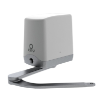
Insert the key and turn it 90° in anticlockwise direction. (Fig.7)
Pull the knob till it is perpendicular to the gearmotor.
4.1 - Installation
4.2 - Fixing
4.3 - Rack assembling
4.4 - Limit switch xing
4.5 - Manual running
 Loading...