15
kobalttools.com
ASSEMBLY INSTRUCTIONS
TABLE STAND ASSEMBLY
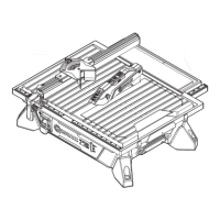
2. First remove washers (KK) and nuts (JJ) from
lower right leg assembly, then attach wheels
(K) to lower right leg assembly (J) with washers
(KK) (one on each side of wheel) and nut (JJ).
Check orientation of wheels and if wheels rub
against frame, reverse orientation. Set wheel
assembly aside for later use.
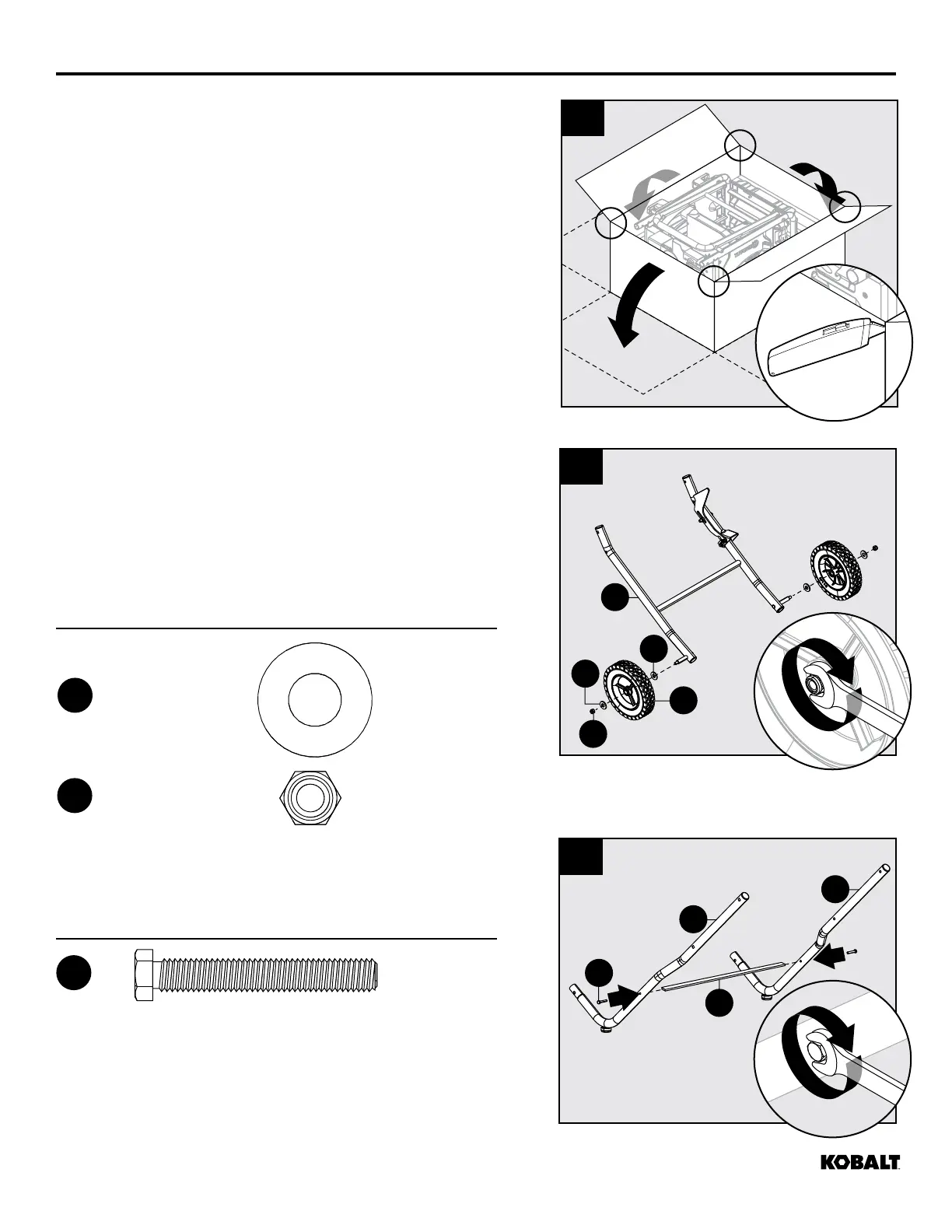
UNPACKING
1. Cut sides of box at all four corners.
IMPORTANT: Before assembly, separate upper
and lower packing trays. Leave base section in
lower tray while completing steps 1 - 8.
1
1
3
CC
M
N
R
2
J
KK
JJ
KK
K
1
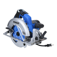
3. Attach left leg cross piece (R) to left front leg (M)
and left rear leg (N) with M6 x 50 bolts (CC).
Hardware Used
M6 x 50mm (1.97")
x 2
CC
2 in. Bolt
Qty. 2
Nut
(preassembled
to lower right
leg assembly)
Qty. 2
Washer
(preassembled
to lower right
leg assembly)
Qty. 4
3 in. Cap screw
Qty. 6
Height adjustment
knob
Qty. 1
8 mm Hex bolt
Qty. 1
1-1/2 in. Cap screw
Qty. 4
Spacer
Qty. 6
Nut
Qty. 10
1 in. hex bolt
Qty. 2
AA BB CC
DD
EE
JJ
KK
FF GG
HH
Hardware Used
Nut
x 2
JJ
2 in. Bolt
Qty. 2
Nut
(preassembled
to lower right
leg assembly)
Qty. 2
Washer
(preassembled
to lower right
leg assembly)
Qty. 4
3 in. Cap screw
Qty. 6
Height adjustment
knob
Qty. 1
8 mm Hex bolt
Qty. 1
1-1/2 in. Cap screw
Qty. 4
Spacer
Qty. 6
Nut
Qty. 10
1 in. hex bolt
Qty. 2
AA BB CC
DD
EE
JJ
KK
FF GG
HH
Washer
x 4
KK
2 in. Bolt
Qty. 2
Nut
(preassembled
to lower right
leg assembly)
Qty. 2
Washer
(preassembled
to lower right
leg assembly)
Qty. 4
3 in. Cap screw
Qty. 6
Height adjustment
knob
Qty. 1
8 mm Hex bolt
Qty. 1
1-1/2 in. Cap screw
Qty. 4
Spacer
Qty. 6
Nut
Qty. 10
1 in. hex bolt
Qty. 2
AA BB CC
DD
EE
JJ
KK
FF GG
HH