TP-7045 3/18c 19Section 4 Exhaust System
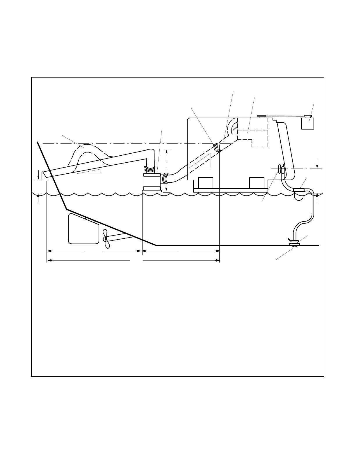
4.3.1 Above-Waterline Installation
Install a customer-supplied silencer with the silencer’s
outlet at a maximum of 3 m (10 horizontal ft.) from the
center of the engine’s exhaust outlet. See Figure 4-3.
Mount a typical silencer with the inlet and outlet
horizontal and with the drain plug down. Use an exhaust
hose pitch of at least 13 mm per 30.5 cm (0.5 in. per
running foot). Some silencers require two support
brackets or hanger straps for installation to stringers or
other suitable structure. Follow the instructions
provided with the silencer. Install any lift (see
Figure 4-3, item 1) in the exhaust line below the engine
exhaust manifold outlet.
Waterline
1
2
4
5
6
7
8
9
10
11
12
13
15
16
3
TP-5856-4
1. Slight lift improves silencing and prevents water backwash
into the silencer (keep below the level of the exhaust
manifold outlet)
2. Silencer (customer-supplied)
3. Exhaust manifold outlet
4. Exhaust m ixer elbow
5. Heat exchanger (locations vary by model)
6. Coolant recovery tank (located on the unit on some models)
7. Maximum seawater pump lift of 1 m (3 ft.)
8. Seawater strainer
9. Seacock
10. Intake strainer
11. Engine-driven seawater pump
12. Minimum exhaust hose pitch of 1.3 cm per 30.5 cm (0.5 in.
per ft.)
13. Maximum distance between silencer and exhaust mixer
elbow of 3 m (10 ft.)
14. Maximum distance between silencer and exhaust outlet of
1.5 m (5 ft.)
15. Minimum exhaust hose pitch of 1.3 cm per 30.5 cm (0.5 in.
per ft.)
16. Minimum exhaust outlet distance above waterline of 10 c m
(4 in.). Note: Vessel fully loaded.
17. Maximum silencer vertical lift of 1.2 m (4 ft.)
18. If the total exhaust length exceeds 4.6 m (15 ft.), Kohler
recommends increasing the exhaust hose to the next
larger diameter. See Figure 4-2 and Figure 4-5.
Note: Data applies to both rear- and side-exhaust installations.
Note: Use two hose clamps on each end of all flexible exhaust
hose connections.
Note: Read the text for complete explanation of dimensions
and other installation considerations.
Note: Damage caused by water ingestion will not be covered by
the generator warranty.
14
17
18
Figure 4-3 Typical Above-Waterline Installation
 Loading...


