TP-7045 3/18c60 Section 9 Paralleling Generator Sets
Voltage and Reactive (kVAR) Power
The Decision-Makerr 3500 controls the generator set’s
output voltage.
The generator set response to the signal varies
depending on the state of its paralleling motorized
breaker.
D Motorized Paralleling Circuit Breaker Open. If the
motorized circuit breaker is open, the output voltage
will change. This would be the case while
synchronizing.
D Motorized Paralleling Circuit Breaker Closed. If
the motorized circuit breaker is closed and the
generator set is operating in parallel with another
power source, this signal will control the kVAR load
provided by the generator.
9.3 Paralleling Set Up
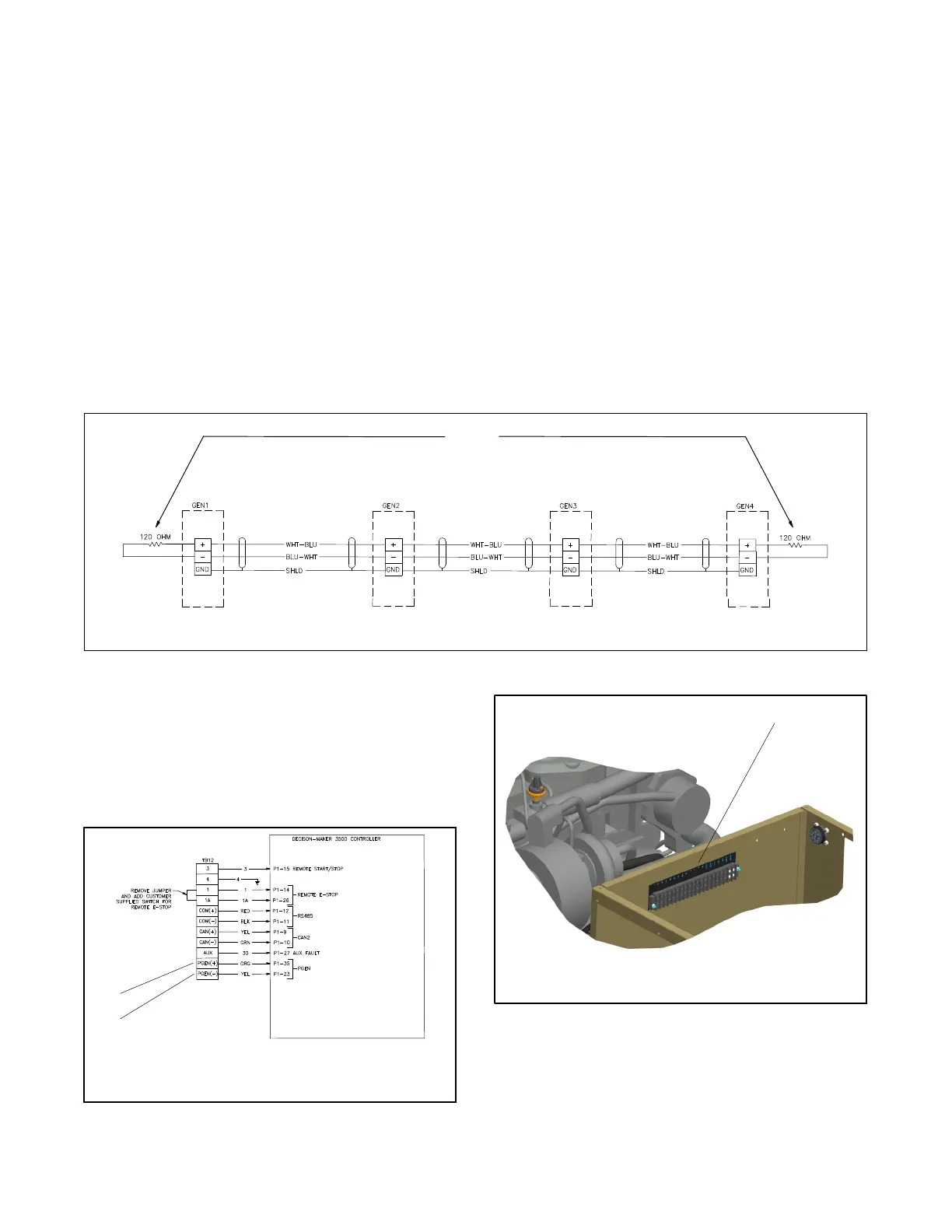
9.3.1 PGEN Communication Wiring
In order to parallel two or more generator sets using
PGEN, a communication wire is required. Use a Belden
cable #9841 (or equivalent) shielded twisted-pair
communication cable. Connect the shield to ground at
one end only. Tighten the connections to 0.5 Nm
(4.4 in. lbs.). The PGEN connection between the
generator sets is always required when the generator
sets connect to a common bus. See Figure 9-3.
NOTE:
Install terminating resistors for any run length over 100 m (328 ft. ).
Install terminating resistors, only if necessary, for any run length between 20--100 m (66--328 ft.).
For best results, do not install terminating resistors for any run length under 20 m (66 ft.).
TB12 TB12 TB12 TB12
Figure 9-3 Paralleling System Interconnection Diagram
PGEN connections are made on terminal block TB12.
TB12 is located in the generator set junction box. See
Figure 9-5 for TB12 location. See Figure 9 -4 for PGEN
connection locations. A small portion of the wiring
diagram is shown in Figure 9-4. See the operation
manual for the complete wiring diagram.
1
ADV-8535-A
1. PGEN (+) connection on TB12
2. PGEN (--) connection on TB12
2
Figure 9-4 Terminal Block TB12 PGEN Connections
1
GM86968-
1. TB12 location
Figure 9-5 TB12 Terminal Block Location
 Loading...


