TP-7045 3/18c20 Section 4 Exhaust System
4.3.2 Mid/Below-Waterline In stallation
Follow USCG Regulations for installing an antisiphon
provision to prevent raw water entry into the engine.
Use the siphon break if the exhaust manifold outlet is
located less than 23 cm (9 in.) above the waterline when
the craft is loaded to maximum capacity. Install the
siphon break at least 31 cm (1 ft.) above the waterline
using the instructions provided with the siphon break kit.
Note: An improperly installed siphon break will cause
engine damage and may void the warranty.
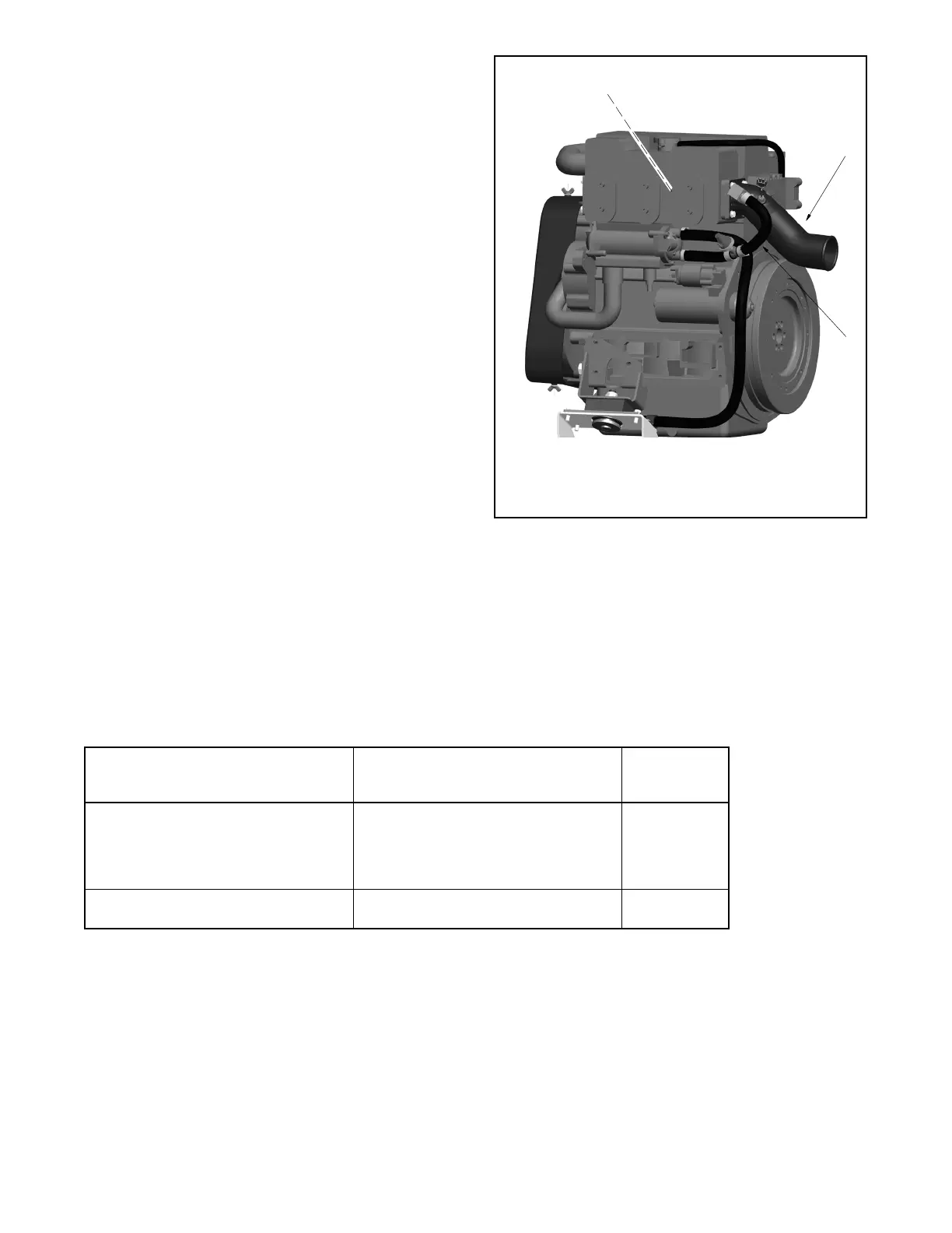
Install the siphon break above the highest point in the
exhaust line between the heat exchanger and the
exhaust mixer. See Figure 4-4 for the siphon break
connection. Support the siphon break and hoses to
maintain their position and function. Allow a slight offset
to clear the stringers or other permanent structures.
Protect the siphon break air inlet from dirt and debris.
Note: To prevent water leakage on the generator set, do
not mount the siphon break directly over the
generator set.
Note: Ensure that the siphon break’s cap is tight before
operating the generator set.
1. Heat exchanger (located inside the manifold)
2. Exhaust mixer
3. Cut hose and connect siphon break and hardware (rotate
the fitting on the mixer if necessary)
1
3
2
GM89516-
Figure 4-4 Siphon Break Connection, Typical
Mount a typical silencer’s base no more than 1.2 m (4 ft.)
below the highest point in the exhaust line. Attach a
separate wood mounting base to the hull stringers or
other suitable structures. Use the silencer
manufacturer’s r ecommendation for securing the
silencer to the hull. Mount the silencer with the outlet not
more than 3 m (10 horizontal ft.) from the engine’s
exhaust manifold outlet. Use a USCG-type certified
marine exhaust hose.
Models without Sound Shield Models with Sound Shield
Exhaust Hose
Diameter
mm (in.)
14EKOZD/12EFKOZD (1 and 3 Phase)
16EKOZD/13.5EFKOZD (1 and 3 Phase)
21EKOZD/18EFKOZD (1 Phase)
21EKOZD/17EFKOZD (3 Phase)
24EKOZD/20.5EFKOZD (1 and 3 Phase)
14EKOZD/12EFKOZD (1 and 3 Phase)
16EKOZD/13.5EFKOZD (1 and 3 Phase)
21EKOZD/18EFKOZD (1 Phase)
21EKOZD/17EFKOZD (3 Phase)
24EKOZD/20.5EFKOZD (1 and 3 Phase)
76 (3.0)
32EKOZD/28EFKOZD (1 and 3 Phase)
40EKOZD/35EFKOZD (1 and 3 Phase)
32EKOZD/28EFKOZD (1 and 3 Phase)
40EKOZD/35EFKOZD (1 and 3 Phase)
89 (3.5)
Figure 4-5 Exhaust Hose Sizes
 Loading...


