TP-7045 3/18c26 Section 5 Fuel System
7 6
1
542
13
12 11
8
9
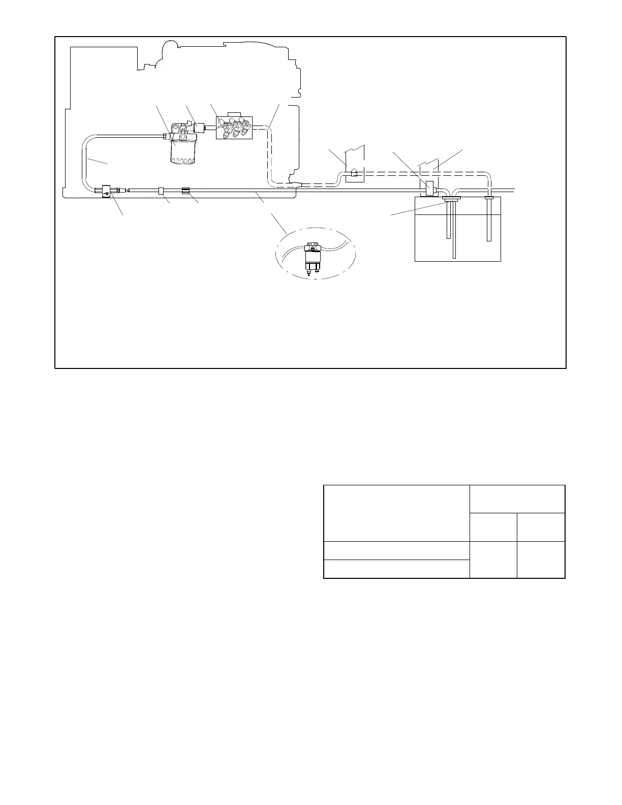
1. Fuel lift pump
2. Secondary filter
3. Fuel solenoid
4. Injection pump (non-service side)
5. Fuel return line
6. Permanent supports for fuel system
components
7. Electric fuel or mechanical check v alve
(customer provided)
8. Dip tube (customer provided)
9. Fuel tank
10. 14--24EKOZD/12--20.5EFKOZD Models:
Primary filter, if equipped (customer
provided).
32--40EKOZD/28--35EFKOZD Models:
Shipped loose with unit for customer to
install.
11. S upport clamp
12. Clamp
13. Fuel supply line
6
10
To
Propulsion
Engine
3
Figure 5-2 Fuel System, Typical
5.2 Fuel Lines
Return the generator set fuel return line to the fuel tank.
Locate the fuel return line as far as practical from the fuel
pickup to allow the tank fuel to cool the return fuel before
delivery back to the fuel injectors. Incoming fuel cools
the injectors to achieve maximum engine efficiency.
Note: Do not tee into the main propulsion engine’s fuel
line.
Note: Fuel Return Dip Tube. Kohler Co. recommends
utilizing a fuel return dip tube located below the
fuel supply dip tube. This will prevent air from
entering the return lines, draining the fuel
injection pump, and thus causing starting failure
or hard starting of the generator set. The dip tube
depth should be at least as deep as the main
engine fuel pick-up dip tube.
Under no circumstances should the propulsion engine
and generator set share pickup or return lines (through a
tee arrangement) that would allow the larger engine to
starve fuel from the smaller engine. It is possible that the
operation of either engine could completely drain the
fuel line of the other engine and make starting difficult.
Use a flexible hose section to connect the metallic line
from the fuel tank to the engine’s fuel pump inlet
connection point. Also, use a flexible hose section to
connect the metallic line from the fuel tank to the fuel
return connection point. The flexible section allows the
generator set to vibrate during operation.
Model
Fuel Line ID Size
mm (in.)
Fuel
Inlet
Fuel
Return
14--24EKOZD/12--20.5EFKOZD
8 (5/16)
min.
6 (1/4)
min.
32--40EKOZD/28--35EFKOZD
Figure 5-3 Fuel Line ID Size
See Figure 5-3 for the ID size of the customer-supplied
fuel line that connects to the fuel pump and fuel return.
Route the fuel lines from the fuel tank in a gradual incline
to the engine—do not exceed the height of the generator
set and do not route fuel lines above the generator set.
Comply with USCG Regulation 46CFR182.20
regarding fuel lines and supports.
See Section 7 for fuel feed pump inlet connection and
fuel return line connection.
 Loading...


