TP-6198 3/1532 Section 4 Controller
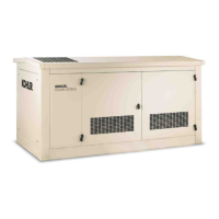
4.2 Controller Display and Keypad
The controller has an LED display and a three-button
keypad. See Figure 4-2. The LED display shows
runtime hours, fault codes, application program version
number, or controller parameters during configuration
and adjustment. See Figure 4-3. The keypad is used to
enter the controller’s configuration and adjustment
menus, and to change the controller settings.
1
2
4
3
1. LED display
2. Select button (for setup and adjustment only)
3. Up and down arrow buttons (for setup and adjustment only)
4. Generator set master switch
GM28707A-C
Figure 4-2 ADC Controller
Item Description
Crank indication Displays CC_1, CC_2, or CC_3 to
indicate the first, second, or third
attempt to start the engine. The last
digit flashes during the crank cycle rest
periods.
Runtime hours Displays total generator set runtime
hours when no other code is displayed.
Fault codes Flashes a 2- or 3-letter fault code to
indicate various fault conditions. See
Section 4.5.
System
parameters
Displays 2-letter codes or 4-digit
alphanumeric codes during system
configuration or adjustment. See
Section 4.9.2.
Application
program
version number
Displays the version number of the
controller’s application program before
entering the configuration or adjustment
mode. See Section 4.9.2.
Figure 4-3 ADC Controller LED Display
A password key sequence is required to enter the
configuration and adjustment menus. Section 4.9
contains the instructions to enter the configuration and
adjustment menus and change the settings using the
controller keypad.
4.3 Master Switch
The generator set master switch is a three-position
(RUN\OFF/RESET\AUTO) rocker switch. The leads
connecting to the master switch are labeled RUN, VBAT,
and AUTO. Check that the three pink connectors are
connected to the terminals on the back of the switch as
shown in Figure 4-4. Be careful not to reverse the RUN
and AUTO leads.
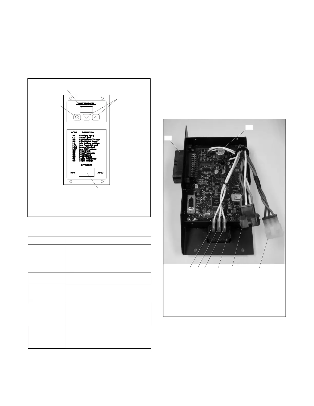
1. Engine wiring harness connector plug (P1)
2. Continuous power mode jumper location (P7)
3. J15 connector
4. J16 connector
5. Generator set master switch
tp6196
1
5 34
2
AUTO
VBAT
RUN
Figure 4-4 Controller Connections
 Loading...
