TP-6198 3/15 61Section 5 Component Testing and Adjustment
5.13 Continuity Checks
Accidental starting.
Can cause severe injury or death.
Disconnect the battery cables before
working on the generator set.
Remove the negative (--) lead first
when disconnecting the battery.
Reconnect the negative (--) lead last
when reconnecting the battery.
WARNING
Disabling the generator set. Accidental starting can
cause severe injury or death. Before working on the
generator set or connected equipment, disable the generator
set as follows: (1) Move the generator set master switch to the
OFF position. (2) Disconnect the power to the battery charger.
(3) Remove the battery cables, negative (--) lead first.
Reconnect the negative (--) lead last when reconnecting the
battery. Follow these precautions to prevent starting of the
generator set by an automatic transfer switch, remote
start/stop switch, or engine start command from a remote
computer.
Short circuits. Hazardous voltage/current can cause
severe injury or death. Short circuits can cause bodily injury
and/or equipment damage. Do not contact electrical
connections with tools or jewelry while making adjustments or
repairs. Remove all jewelry before servicing the equipment.
Note: Disconnect the generator set battery before
performing continuity checks to prevent damage
to the ohmmeter.
To further check generator set components, disconnect
the battery and remove wiring harness plugs from the
controller circuit board. Refer to the wiring diagrams in
the wiring diagram manual and use an ohmmeter to
check for continuity and good ground connections. A
zero reading on the ohmmeter indicates continuity. No
ohmmeter reading indicates very high resistance or an
open circuit.
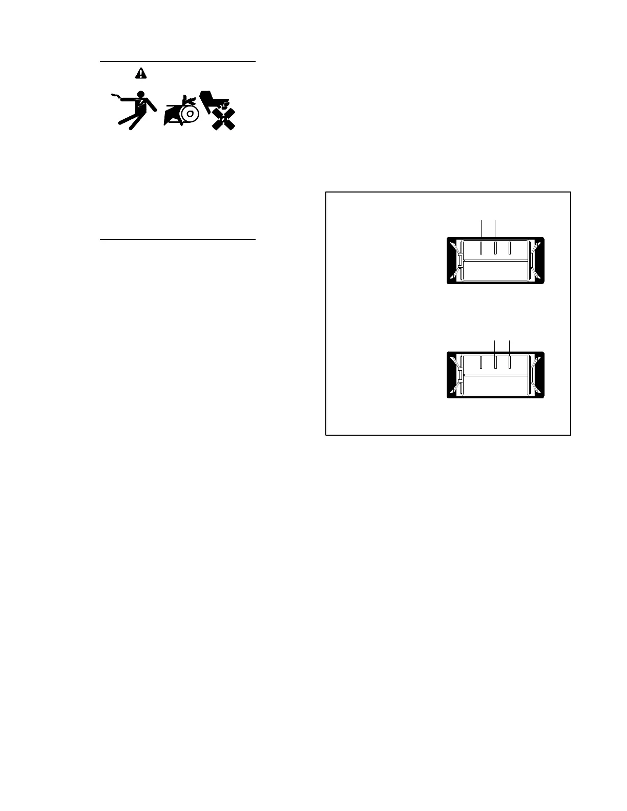
Figure 5-19 illustrates the generator set master switch
continuity with the switch in the RUN and AUTO
positions.
tp6196
321
321
Master Switch in
RUN Position
Master Switch in
AUTO Position
Zero ohms (continuity) across RUN
and COM terminals
Zero ohms (continuity) across
COM and AUTO terminals
AUTO
RUN
COM
AUTO
RUN
COM
Figure 5-19 Generator Set Master Switch Continuity
Checks (back view of switch)